
|

|
Forum Index : Microcontroller and PC projects : photos from sparky the inverter
| Author | Message | ||||
| sparkey Senior Member Joined: 15/06/2011 Location: AustraliaPosts: 819 |
all the photos i can load atm till i get a tripod to mount my camera on sorry about the quality its a phone after all all these r under "soldering iron " so have a squiz i will attempt some better photos but this is what i have atm regards sparkey technicians do it with least resistance |
||||
| VK4AYQ Guru Joined: 02/12/2009 Location: AustraliaPosts: 2539 |
Cyberspace got your photos or maybe it was Win 7 that ate them. Bob Foolin Around |
||||
| sparkey Senior Member Joined: 15/06/2011 Location: AustraliaPosts: 819 |
here is the switching circuit working at present.... 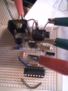
technicians do it with least resistance |
||||
| aargee Senior Member Joined: 21/08/2008 Location: AustraliaPosts: 255 |
Sparkey, What sort of veroboard is that? It looks like double sided (if so, I'm interested knowing where to get it!) or is it just painted strips on the board? - Rob. For crying out loud, all I wanted to do was flash this blasted LED. |
||||
| sparkey Senior Member Joined: 15/06/2011 Location: AustraliaPosts: 819 |
sorry to say its single sided but i think that its not a hard ask maybee you could cut two pieces and do it that way ..but somebody prolly makes double sided ....regards sparkey... technicians do it with least resistance |
||||
| sparkey Senior Member Joined: 15/06/2011 Location: AustraliaPosts: 819 |
if your looking for more of my pic`s look at "soldering iron by sparkey but i will be posting most of my gear on this topic from now on ...regards sparkey.... technicians do it with least resistance |
||||
| vasi Guru Joined: 23/03/2007 Location: RomaniaPosts: 1697 |
That was brilliant, didn't thought of that... Hobbit name: Togo Toadfoot of Frogmorton Elvish name: Mablung Miriel Beyound Arduino Lang |
||||
| sparkey Senior Member Joined: 15/06/2011 Location: AustraliaPosts: 819 |
just cut 2 pieces the same size and just around the corners of the boards add a drop of some type of glue ..superglue and get an aligator clamp or g clamp to whold the bords together and leave it over night ...regards sparkey dont foget to leave the copper sides out .... technicians do it with least resistance |
||||
| sparkey Senior Member Joined: 15/06/2011 Location: AustraliaPosts: 819 |
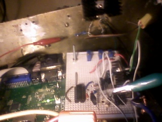
here are some pics with the switching board inserted into the case and a couple of other pics...regards sparkey....still a works in progress have to sort out some pc`s for the small regs yet ...... 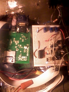
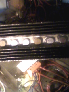
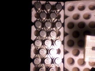
technicians do it with least resistance |
||||
| sparkey Senior Member Joined: 15/06/2011 Location: AustraliaPosts: 819 |
here is the picture of a 2n3055 with 13 volt zenner to give a 13 volt rail as shown its upside down so you cant actully see the 3055 but its regulating down from the main buss 36 volts and also is the 14 volt rail regulator on the black heatsink thjen it feeds a 5 volt reg to power the switching cct....regards sparkey;.... 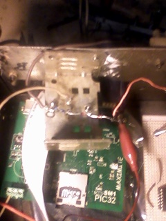
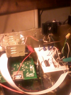
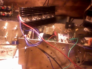
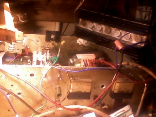
and yes its still aworks in process but it is functioning as you se it here it needs alittle tyding up once i can get it of my bench and onto a table where i have 360 degreese access....regards... technicians do it with least resistance |
||||
| sparkey Senior Member Joined: 15/06/2011 Location: AustraliaPosts: 819 |
] :::this is the discription of the switching cct:::: the maxi puts out the square wave to feed the 4013 flip flop via a 100nf bypass cap from there the outputs of 'q' and 'q-' are fed to the two bd 139 npn transistors the outputs are then fed into the relay the relay has a charge up cct time before the outputs are activated reason for this is to give the maxi time to load and run the "pwm" program so as to stop the out put running free the transformer is a centre tapped 64 volt hence to say that the collectors of the array tr`s are connected on one bank at the outer sides of the transformer with the centre tapp connected to the input positive from the battery`s and the emmittes connected to negative "gnd"...two banks required ..this gives a modified square wave out put... 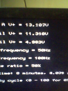
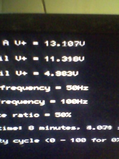
the outputs from the relays are fed to the bases of the two sets of output drive transistor banks for the main chopping voltage and current switching of the heavy currents feeding the transformer.... there is a leak feed to a 1meg trimpot via a 100nf bypass cap off pin 1 "q" so that reads the output back to the maxi mite frequency counter this gives the correct frequency of one half cycle that is "output is at 100Hz ,,so the report freq is 50 hz this is the tru freq at the 240 volt line well very close to 50 hz ..i`m not game to try latching the 240 volt to the maxi so the output of the 4013 will have to suffice... you will also notice the three trimpots they are for reading other voltages around the circuit and reporting back to the maximite.... 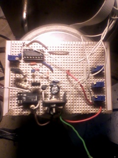
here is the finished board except one voltage rail which i am yet to decide what that will be 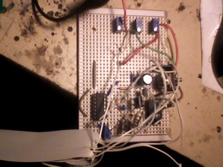
here are some of the disply pictures sorry about the way they are taken but i only have my mob to take pics..... 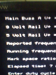
technicians do it with least resistance |
||||
| sparkey Senior Member Joined: 15/06/2011 Location: AustraliaPosts: 819 |
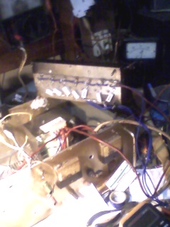
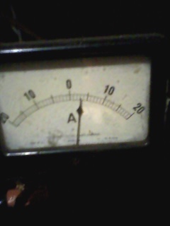
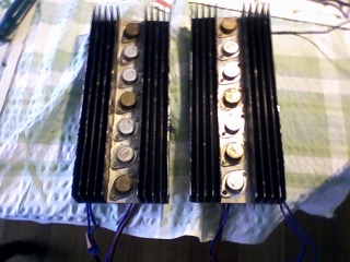
new pics here are some more picks the only thing running off my batterty`s is the computer here is a pict of my main amp meter and yes its wired backwards ..never bothered to change the poles round also you can see the altron driving the switch board cct and a rear look at the transistor array ..i also use a "k-v-m" switch with the mouse plugged straight to the "pc" and the kb and vga plugged to the maxi so i can switch from either... 
technicians do it with least resistance |
||||
| sparkey Senior Member Joined: 15/06/2011 Location: AustraliaPosts: 819 |
also i would like to add that at present running the inverter itself and the maximite and the computer and 19 inch "l.c.d" screen and the kvm switch i am using aproxx 4 amps from the batterys ...in the day time i am usually getting an average of four amps from green power....regards sparkey...... technicians do it with least resistance |
||||
| sparkey Senior Member Joined: 15/06/2011 Location: AustraliaPosts: 819 |
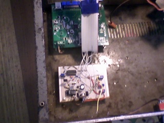
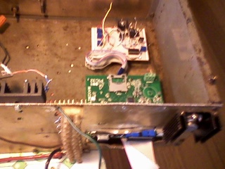
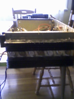
here are hopefully the final photos of the inverter with the boards mounted correctly and still a couple more to come but this should be the last pics....all hail "murphey"... 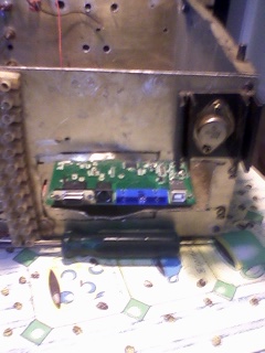
technicians do it with least resistance |
||||
| sparkey Senior Member Joined: 15/06/2011 Location: AustraliaPosts: 819 |
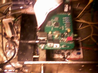
atm i only have my altronics version running the inverter heres a couple of pics 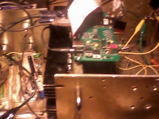
technicians do it with least resistance |
||||
| sparkey Senior Member Joined: 15/06/2011 Location: AustraliaPosts: 819 |
here`s my inverter and screen shot sorry about the qualty but thought some would app the whole box and dice 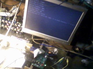
technicians do it with least resistance |
||||