| Author |
Message |
Bryan1

Guru

Joined: 22/02/2006
Location: AustraliaPosts: 2297 |
| Posted: 06:36am 16 Jul 2026 |
 Copy link to clipboard Copy link to clipboard |
 Print this post |
|
G'Day Guy's,
Well with the GUI Controls now available on HDMI with my recent coding for the Surface Grinder Project when I started thinking about this new project the fact we have 4 axis to play with I do have a few spare 3 jaw chucks so a new A axis project is going to happen and just ordered a stepper motor and DM556 micro stepper for the project.
Now on my Surface Grinder Project Lyle suggested a 1K/22k with a BC337 translator to the DIR/STEP outputs so does this give full isolation to the pico pins ?
With the new board to be made for the breakout board to my CNC I will have a go at doing a schematic first so it can go past the brains trust before committing to design the board.
Regards Bryan |
| |
DaveJacko
Senior Member

Joined: 25/07/2019
Location: United KingdomPosts: 107 |
| Posted: 08:55pm 17 Jul 2026 |
Copy link to clipboard |
Print this post |
|
Bryan, I suggest you use opto-isolators, get familiar with the concept of current transfer ratio, CTR. Even I understand this. BC337's give no isolation, and just short-circuit all their pins together if they fail.
Try swapping 2 and 3 over |
| |
Bryan1
Guru
Joined: 22/02/2006
Location: AustraliaPosts: 2297 |
| Posted: 06:11am 18 Jul 2026 |
Copy link to clipboard |
Print this post |
|
Well Lyle has been helping me along and has suggested using 2 pico's, now where a 2350A chip is just a few dollars this PICO 3 Computer is much more expensive.
While I was waiting for my daughters this morning got thinking about this, so if we set the 2350A on my stepper board to USB so it can accept CDC input/output then it would be easy to transmit the G-code line by line via the USB. So the big question with hte PICO 3 USB Hub can it be used for this purpose.
Now being able to scan a part and save it to a file where the area is defined then the Y axis is set at the end of each pass to move y$ The X axis stepped slowly until the microswitch is closed then the Z axis it moved higher and the microswitch constantly tested for when it opens.
So each X movement on completion can broadcast it to the PICO 3 where it can be saved to a file or with some coding drawn on the monitor so one can verify the scan.
My soldering iron handpiece should be here soon so I can get the V2 stepper board made and then the surface grinder project can be completed.
Regards Bryan |
| |
mozzie
Guru
Joined: 15/06/2020
Location: AustraliaPosts: 469 |
| Posted: 02:32pm 18 Jul 2026 |
Copy link to clipboard |
Print this post |
|
G'day,
I have been working on this in the background and have made a few false starts at getting it running.
Unfortunately life and figuring out how to make a living keeps getting in the way, not to mention about 1000000 other half baked ideas running around the grey matter 
So the basic idea is to have 2 controllers, one a CNC controller on the machine, and one as a G-Code transmitter / HMI:
Use a standard PICO2 at the CNC machine end as a stand alone controller running the STEPPER SYSTEM under MMBasic, this:
Accepts G-Code and Outputs STEP/DIR/EN to the Stepper Drivers.
Monitors the Homing / Limit / Stop switches and transmits status and position.
The G-Code transmitter end can be pretty much anything, but a PICOMITE HDMIUSB or a PC make the most sense:
Runs a simple MMBasic / Python program to parse and send G-Code to the CNC controller.
Accepts return strings / position information / status from the CNC controller.
If we use a standard PICO2 at the CNC end we have the option of using the USB-CDC to communicate with the G-Code transmitter or using a USB-TTL232 converter, this gives us as an example:
GP00-GP01 USB-TTL
GP02-GP03 I2C RTC + OLED status display? + Extra I/O via expanders
GP04-GP06 X Axis EN/STP/DIR
GP07-GP09 Y Axis EN/STP/DIR
GP10-GP12 Z Axis EN/STP/DIR
GP13-GP15 A Axis EN/STP/DIR
GP16-GP21 X-X,Y-Y,Z-Z Limits
GP22 E-Stop
GP26-GP28 AUX Analog / Encoder / Limits / Spindle
OR:
GP00-GP01 USB-TTL
GP02-GP03 I2C RTC + OLED status display? + Extra I/O via expanders
GP04 SPINDLE
GP05 ENABLE
GP06-GP07 X Axis STP/DIR
GP08-GP09 Y Axis STP/DIR
GP10-GP11 Z Axis STP/DIR
GP12-GP13 A Axis STP/DIR
GP14-GP15 Spare
GP16 E-Stop
GP17-GP19 X,Y,Z Limits
GP20-GP28 AUX Analog / Encoder / Limits
For more I/O use an RP2350B instead, although 22 I/O from the PICO2 should be enough for most systems.
The advantage of using the USB-TTL converter is we can opto-isolate the USB system and thus protect the G-Code transmitter from any spikes etc, this is my current plan after seeing several PC motherboards and LPT cards damaged by spikes on what where supposed to be isolated systems, I think it is much better to destroy an $11AUD PICO2 than anything more expensive.
Also means we only need one PICO COMPUTER3 / PC / Monitor for all the different machines.
This is still a work in motion so any ideas welcome.
Regards, Lyle. |
| |
Bryan1
Guru
Joined: 22/02/2006
Location: AustraliaPosts: 2297 |
| Posted: 10:43pm 18 Jul 2026 |
Copy link to clipboard |
Print this post |
|
Lyle as I did make the V2 CNC board we may aswell use that and as we are using it as a slave no LCD will be needed which does leave the 12 pin LCD connector free to use. 
I have an old USB-TTL converter in a drawer that has sat there for over a decade which I can use and GP8, GP9 are brought out to a header too.
I am slowly getting my head around this probe for scanning parts which could also be a good tool for debugging etc as the USB-TTL connection can be fine tuned using this method.
Now as we are receiving data from the V2 CNC board a good idea would be to draw it on the screen then that bit of code can be used for normal operation where when making a part it is drawn on the screen.
Yes a heap of grey matter is going to be used to work this out as reading that python book is bringing back memories from a very long time ago.
Regards Bryan |
| |
Bryan1
Guru
Joined: 22/02/2006
Location: AustraliaPosts: 2297 |
| Posted: 07:18am 18 Aug 2026 |
Copy link to clipboard |
Print this post |
|
Ok had some fun getting back to this project and as I still had the LCD connected to my V1 CNC board used that with claude to make a start.
So basically the 2350A on my CNC board is going to be slave via COM3 and sit and wait for a command from the master pico 3 board. The first thing was testing the COM3 to see if works and my first attempt of sending a "?" worked
Ran out of time today as I have that car meeting tonight now the mornings first job is getting V3 CNC board all soldered up and connected to the DM556 steppers on my CNC then the fun can really start as Claude is trying to run me at 150% so this CNC project should take too long to get going.
Once we get the gui going for the pico 3 then working with the slave the LCD will be great for debugging then once it's all sorted a LCD won't be needed.
Regards Bryan |
| |
PhenixRising
Guru
Joined: 07/11/2023
Location: United KingdomPosts: 2100 |
| Posted: 02:18pm 18 Aug 2026 |
Copy link to clipboard |
Print this post |
|
I have an Amada CNC Press Brake and Amada Laser Cutter on the way; I want to build metal enclosures for my PicoMites (EMI protection). Not sure if this is a concern for stepper-motor CNCs (?) |
| |
mozzie
Guru
Joined: 15/06/2020
Location: AustraliaPosts: 469 |
| Posted: 03:47pm 18 Aug 2026 |
Copy link to clipboard |
Print this post |
|
G'day,
Bryan,
Looks like you and Claude are steaming along, sorry to see things didn't work out at the car club, you can almost bet if something is going to play up it'll be in front of an audience.
In a previous job I did the training course and demo's on the Jetting / Hydro-Excavation trucks I was involved in building and programming, I can gaurantee every time I had a last minute doubt about a truck it would raise it ugly head at the worst possible moment...
Looking back at some notes regarding the Dual-Pico-CNC system, I was intending using the following data block:
From CNC to HMI:
Machine position sent every 250mS
Start 1 Byte &hAA (&b10101010)
Peek(Stepper X) 8 Bytes -9999.99 to +9999.99
Peek(Stepper Y) 8 Bytes -9999.99 to +9999.99
Peek(Stepper Z) 8 Bytes -9999.99 to +9999.99
Peek(Stepper A) 8 Bytes -9999.99 to +9999.99
Peek(Stepper Buffer) 4 Bytes 0 to 1024
Peek(Stepper Status) 3 Bytes 0 to 255
Peek(Stepper Active) 3 Bytes -1 to 255
ChkSum 3 Bytes 0 to 999
Stop 1 Byte &hA5 (&b10100101)
CR 1 Byte &h10
Total 48 Bytes (50mS @ 9600bps / 25mS @ 19200)
Error Messages - Sent direct.
From HMI to CNC:
Page 1 shows controls / sends G-Code / messages on bottom 4 lines (Scrolls)
Page 2 shows returned messages
The code on the CNC end should be quite simple, depending on how much parsing of the G-Code is done at the HMI end. I suggest as much as possible.
Also you can keep audio (PIO2) on the HMI Pico because its not running the stepper system at this end.
I will be using a USB-TTL converter and opto couplers for the serial link, this will make the CNC and HMI pico's completely opto isolated and is the reason for the 9600/19200 baud rate. This should be ample.
Phenix,
Any chance I could mis-direct the postage on those 2 CNC's down under  Extremely Jealous Extremely Jealous 
Noise is indeed a major concern with stepper motor drives on CNC machines, a lot of the low end / hobby gear uses non screened cabling for the drives and the current control is often chopper driven so VERY noisy.
The idea with the Dual-Pico-CNC is to keep the CNC pico close to the drives and the wiring as short as possible, and have the HMI pico opto isolated and remote.
Even the setup below gave me grief until a 2.5mm earth was connected from the machine to the control box (with the lid on)
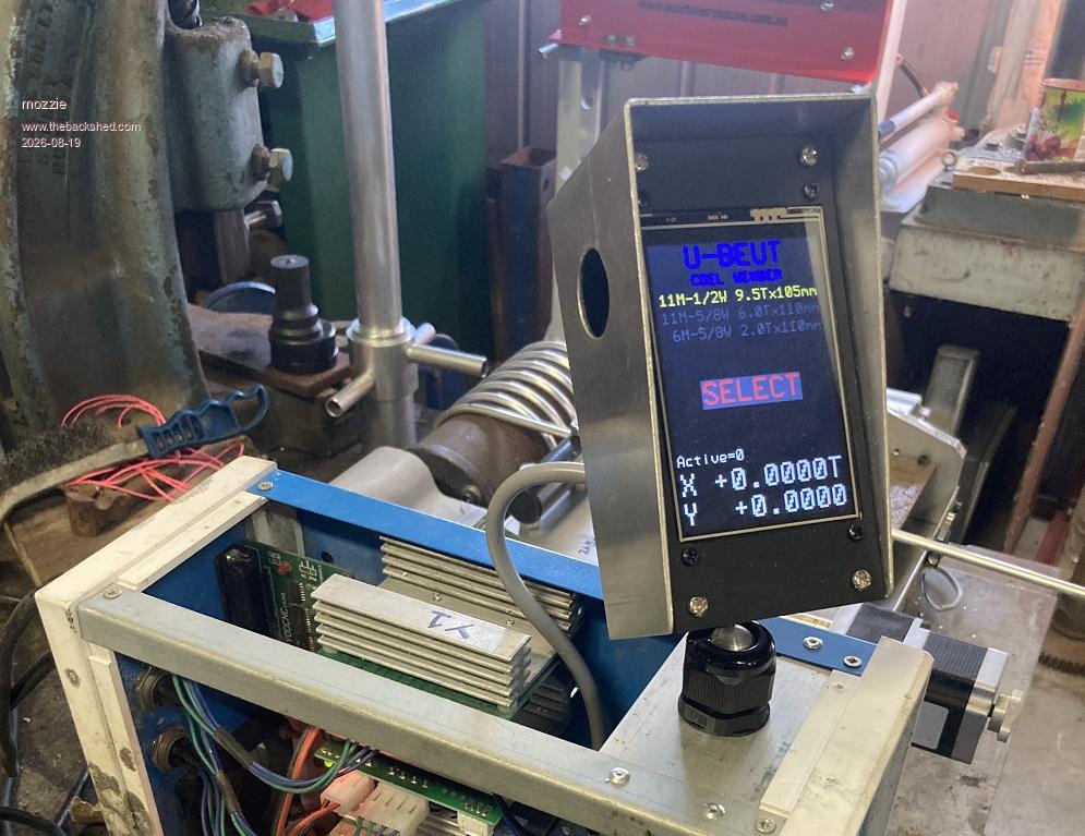
Lucky enough to have a manual guilotine and folder, makes this kind of thing a piece of cake.
Will be very interested to see what you build.
Regards, Lyle. |
| |

 Notice. New forum software under development. It's going to miss a few functions and look a bit ugly for a while, but I'm working on it full time now as the old forum was too unstable. Couple days, all good. If you notice any issues, please contact me.