
|
|
Forum Index : Microcontroller and PC projects : Picomite PS2 keyboard problem
| Author | Message | ||||
| strangepapyrus Newbie Joined: 24/06/2025 Location: United KingdomPosts: 3 |
Hi, Electronics is a fairly new hobby for me and this is my first post here. Please could anyone offer some advice to help me out? Thank you. I decided to have a go a building the Picomite VGA and have been partially successful. I ordered the PCBs to the UK from JLCPCB and the other parts sourced from various suppliers. The VGA works, but not the keyboard. I have 5 volts out from the port so the MOSFET level shifting circuit must at least be partially working? The system boots, I can see all the post boot info on screen and a cursor, but absolutely nothing from the keyboard. Thinking I must of done something wrong somewhere, I had a second board, so built a second picomite from scratch, including a second pico ....... and exactly the same. There does not seem to be power to the keyboards, apart from an initial flash of the leds on my Fujitsu keyboard at boot, CAPS LOCK, does not illuminate when pressed for example, and no output onscreen. I have tried different keyboards. I have newer Fujitsu keyboards (x2) and an older Compaq keyboard (x1) - all PS2 wired, no adapters. I have tried soldering on different PS2 ports and different MOSFETS from different suppliers. I've tested the resistors and all seem good. I've tested the output from the PS2 port. I've tried newer and older firmwares. I've swapped the picos around and all to no avail. The power supply is one I used to use on a raspberry pi, 5V 3000mA output. I am starting to lean towards the PCBs being bad as I'm a bit stuck as to what's going on, so if anyone could offer any advice I'd be extremely grateful. Thanks, Martin 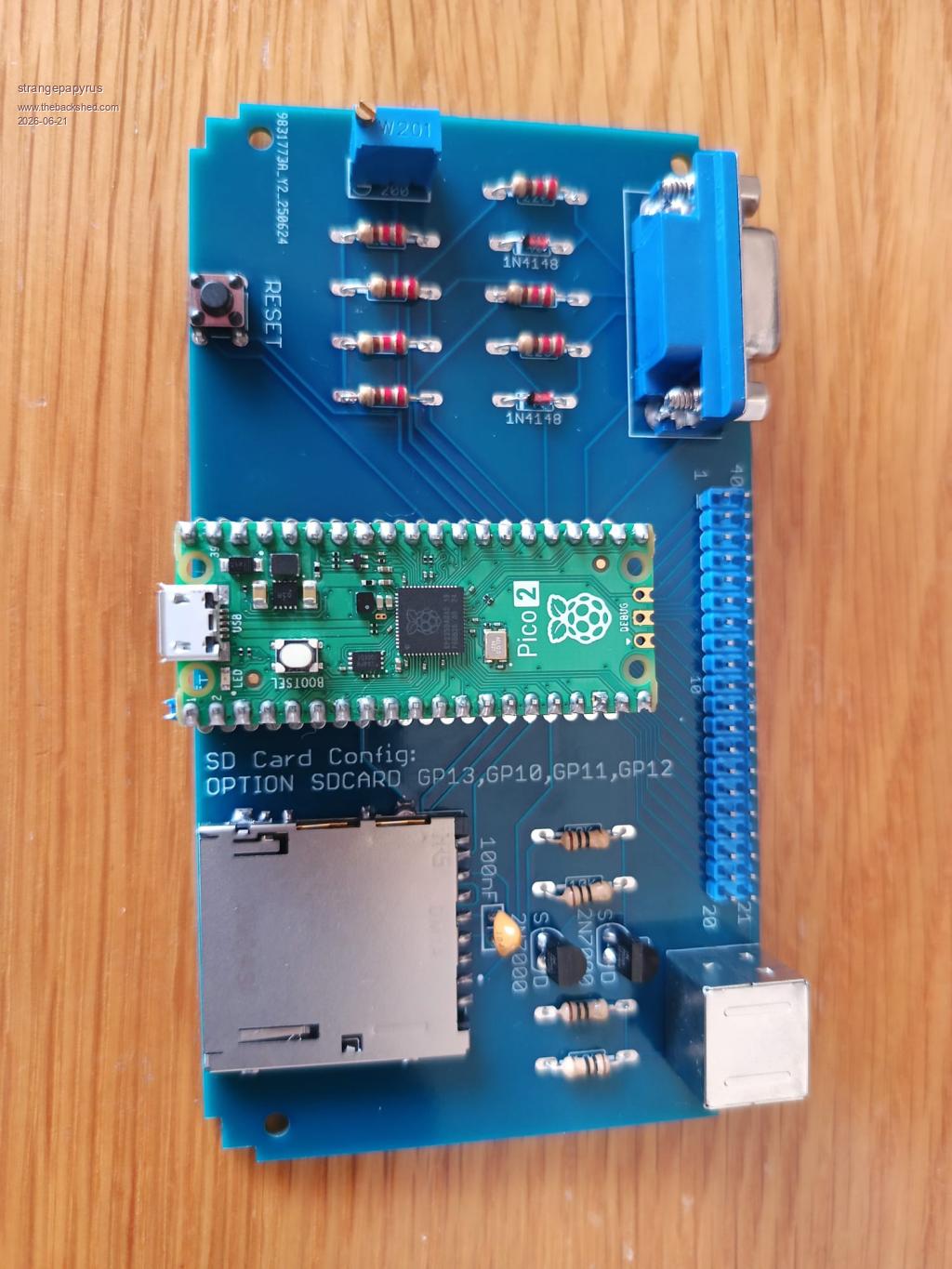 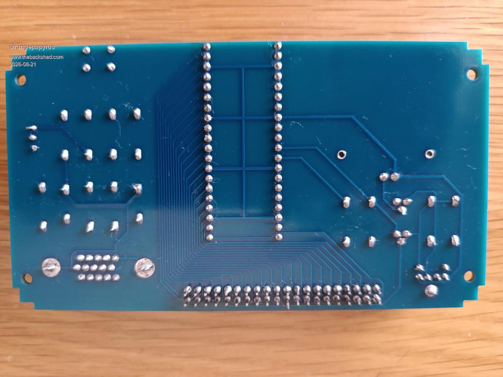 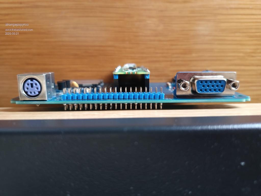 |
||||
| matherp Guru Joined: 11/12/2012 Location: United KingdomPosts: 11540 |
What firmware version are you using? Before anything else type "OPTION RESET VGA DESIGN 1" and then try again. |
||||
| robert.rozee Guru Joined: 31/12/2012 Location: New ZealandPosts: 2530 |
hi Martin, welcome to the forums. what are the colour bands on the four resistors near the 2N7000 transistors? from the photo they appear to be brown-black-black-gold, which would indicate a value of 10 ohms each. they should be 10,000 ohms each, which are instead coded as brown-black-orange-gold (the gold indicates 5% tolerance parts, which is unimportant). you do appear to have inserted the 40-pin blue header (located between the keyboard and VGA sockets) with the long ends of the pins the wrong way round, but this does not matter too much at the moment. otherwise, you have done a very nice job of the assembly and soldering  cheers, rob :-) Edited 2026-06-21 22:15 by robert.rozee |
||||
| phil99 Guru Joined: 11/02/2018 Location: AustraliaPosts: 3294 |
Rather than trying to de-solder the entire header it may be possible to push the pins through one at a time. With the board upside down on a firm surface re-melt the solder and press down to 1mm above the PCB. The blunt end of a skewer, or better still a carpenters panel-pin punch should do the job. As Rob said they do look like 10Ω resistors. If so that could damage the Pico if powered up for long. I think Peter has set 8mA current limits for the pins but it will still be heating the chip. |
||||
| strangepapyrus Newbie Joined: 24/06/2025 Location: United KingdomPosts: 3 |
Oh my goodness. What a plonker. I need better glasses and missed that K in the list of parts in the design construction notes. I have indeed put 10 rather than 10,000 ohm resistors in! Thank you all so much for the help and suggestions. I really appreciate it. Sometimes forums aren't very kind to noobs, so thanks for not being like that. I'll get some of the right resistors in and get back to you with hopefully some success! All the best, Martin |
||||
| PhenixRising Guru Joined: 07/11/2023 Location: United KingdomPosts: 1962 |
This community and MMBasic is the best thing happening in the MCU world. Period. Spread the word Impossible is nothing  |
||||
| JohnS Guru Joined: 18/11/2011 Location: United KingdomPosts: 4336 |
rob - well spotted! John |
||||
Grogster Admin Group Joined: 31/12/2012 Location: New ZealandPosts: 9977 |
Nice one Rob, and welcome Martin.  Newbie questions are welcome here. The only serious rule here is: "No politics". No discussions or flame-wars/arguing about politics or government etc. To quote Gizmo(the forum owner/operator): "There are other forums for that."  Other then that, feel free to post any questions you like, including newbie ones. We all had to ask them ourselves at some point.  Smoke makes things work. When the smoke gets out, it stops! |
||||
| Volhout Guru Joined: 05/03/2018 Location: NetherlandsPosts: 5942 |
Hi Martin, It will be hard to undo now, but from the photo's it looks like the 40 pin connector is placed upside down. The short pins should be soldered in the PCB. The long side connects to dupont wires, or connectors. Volhout P.S. your soldering quality is very nice. Or is it machine soldered ? Edited 2026-06-23 18:14 by Volhout PicomiteVGA PETSCII ROBOTS |
||||
| robert.rozee Guru Joined: 31/12/2012 Location: New ZealandPosts: 2530 |
easiest solution - once the keyboard issue has been sorted out - would be to first trim the excess length off the pins on the underside of the PCB, then simply lever off the blue 20x2 plastic part using a small flatblade screwdriver, no heat required. the exposed pin length on top (with the plastic removed) should just about be sufficient to plug on dupont/berg connectors. the downside to this approach is that if you ever want to resolder one or more of the pins, there will be nothing holding them all in alignment. cheers, rob :-) |
||||
| matherp Guru Joined: 11/12/2012 Location: United KingdomPosts: 11540 |
It is easier enough to remove and replace the connector with just a soldering iron. apply the iron to each pin in turn and pull that one pin out with a pair of pliers. Once they are all removed many of the holes will be blocked with solder. You can use solder-wick to clear them out but my patented "wick-less" method is as follows: Apply the soldering iron to a blocked hole so it is properly melted then hit the board against the desk or similar hard surface. The sudden deceleration of the board will cause the melted solder will fly out of the hole leaving it perfectly clean. Edited 2026-06-23 21:34 by matherp |
||||
| Volhout Guru Joined: 05/03/2018 Location: NetherlandsPosts: 5942 |
Peter, That is my method also. You cannot patent it anymore.... Volhout PicomiteVGA PETSCII ROBOTS |
||||
| strangepapyrus Newbie Joined: 24/06/2025 Location: United KingdomPosts: 3 |
Thanks for the tips about the 40 pin connector. I will have a try this evening and see how it goes. Still waiting for my 10K resistors to arrive. This was my first PCB order and I originally put 2 in the basket and thought crikey, as it was about £15 I think. So I made it 5, then 10, then 15, thinking economy of scale but the price was going up and up. Lastly I put 20 and suddenly the price dropped to about £7.50 for the lot. Glitch?? So I still have about 18 boards, which the way I'm going I might yet need 🤣 especially if I damage a board trying to remove this header. Seriously though I do have some spare if anyone needs one. Apart from the pico, I found the most expensive part was the SD Card Reader. Thanks, Martin |
||||
| Bleep Guru Joined: 09/01/2022 Location: United KingdomPosts: 810 |
I think initially what Rob says is your best option for the pins. Then if you find the exposed pins are not long enough, yes you can try desoldering them one at a time. But any form of desoldering will require you to get a new 40pin connector, anyway, because all the pins will now be covered in solder/bent/otherwise dammaged. Regards Kevin. |
||||
| phil99 Guru Joined: 11/02/2018 Location: AustraliaPosts: 3294 |
The other option that doesn't require removing them, push each pin through to the right height. |
||||
| The Back Shed's forum code is written, and hosted, in Australia. | © JAQ Software 2026 |
