|

|
Forum Index : Microcontroller and PC projects : Cheap efficient adjustable linear power supply
| Author | Message | ||||
| Volhout Guru Joined: 05/03/2018 Location: NetherlandsPosts: 4343 |
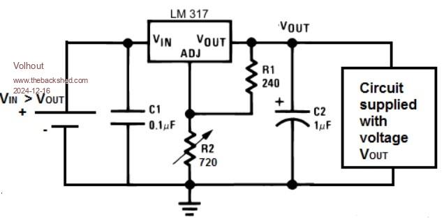
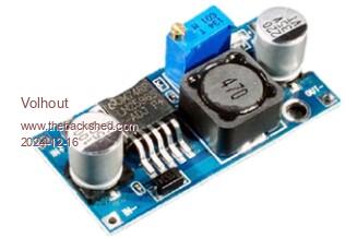
This post is just an idea that I want to share to the forum. When time permits it will grow to a picomite based adjustable power supply. But the basis is shared here in this post. Lab Bench Power Supply Lab Bench power supplies are in 2 categories, 1/ Linear power supplies ( mostly famous because of their low ripple and noise) but typically have a bad efficiency (heatsinks that get warm). A typical application is the LM317 linear regulator for a small 1A 30V supply. Similar to this:  2/ Switchmode power supplies ( famous for their good efficiency ( but poor noise behaviour). For similar powers you can use the cheap LM2596 boards as depicted below.  The schematics are found on the internet, and are these:  The combination of a pre-regulator and a post regulator. Very good results can be achieved when the linear regulator is given the optimal input voltage to perform it's task, something like 3V dropping on the LM317. That can be achieved by combining the switching pre-regulator and the linear post regulator as below. Remove the potmeter from the LM2596 board.  The adjustment of the switching regulator is replaced by a circuit that makes it track the output voltage for the linear regulator. The 680 ohm resistor deternings the LM317 drop voltage.  I purchased the LM2596 board for 1 euro, and the LM317 for 50 cents. The whole power supply is below 2 dollar (except for the 36V source). This idea works fine, the LM317 needs only a very small heatsink, for a continuous 1A output. For real low noise, an LC filter between LM2596 and LM317 is needed. This is not a complete bench power supply, but the idea forms the basic for the power supply in development. It is just that somebody might find this beneficial. Volhout Edited 2024-12-16 23:50 by Volhout PicomiteVGA PETSCII ROBOTS |
||||
| robert.rozee Guru Joined: 31/12/2012 Location: New ZealandPosts: 2358 |
see also: https://sound-au.com/articles/preregulators.htm#s5 cheers, rob :-) |
||||
| Mixtel90 Guru Joined: 05/10/2019 Location: United KingdomPosts: 6904 |
I have a circuit somewhere that was in an old magazine. It has a low frequency prereg that charges the reservoir capacitor via a MOSFET then cuts off the charge partway up the cycle (controlled by a thyristor). That maintains the voltage on the cap at a controlled level. A transistor measures the voltage across the linear regulator that follows it. I find it very interesting as there is no HF generation at all. Obviously, it's bulky as it uses a conventional mains transformer. Apparently the transformer can be a bit "buzzy" due to the unusual load on it, only charging the reservoir in pulses. I'll see if I can find it. Mick Zilog Inside! nascom.info for Nascom & Gemini Preliminary MMBasic docs & my PCB designs |
||||
| Volhout Guru Joined: 05/03/2018 Location: NetherlandsPosts: 4343 |
Robert, Some of thesecircuits look the same but operate different. The circuit proposed above is a linear feedback system that does not need any tuning since it relies on the feedback gain and phase that was originally designed. The circuits in your article increase the gain, and therefore require careful tuning to maintain stability. Volhout Edited 2024-12-17 04:09 by Volhout PicomiteVGA PETSCII ROBOTS |
||||
| Mixtel90 Guru Joined: 05/10/2019 Location: United KingdomPosts: 6904 |
This isn't the original, but it's more or less the same circuit. Blackdog didn't originate it either, it's far older. IIRC it was in Practical WIreless. Try this - it explains it There's a link to EEblog on there, which shows the original circuit from the magazine. There is also quite a bit more info from Blackdog, including a Spice model. . Edited 2024-12-17 05:44 by Mixtel90 Mick Zilog Inside! nascom.info for Nascom & Gemini Preliminary MMBasic docs & my PCB designs |
||||
| phil99 Guru Joined: 11/02/2018 Location: AustraliaPosts: 2176 |
Toshiba used something similar in their VCRs. As the thyristor controlled the transformer primary in their version standby power averaged about 50mW when most of the others at that time were around 1 or 2W. |
||||
| Mixtel90 Guru Joined: 05/10/2019 Location: United KingdomPosts: 6904 |
It's a design that I intended trying at one point but never got round to it. Others seem to have had it working pretty well, sometimes with a little tuning of the bc capacitor on the transistor to make it work optimally with some transformers. Mick Zilog Inside! nascom.info for Nascom & Gemini Preliminary MMBasic docs & my PCB designs |
||||
| Volhout Guru Joined: 05/03/2018 Location: NetherlandsPosts: 4343 |
Mick, Pre-conditioning with SCR's cannot be used anymore due to the terrible power factor. Anyway, you have given me lots to think about. Thank you. Volhout PicomiteVGA PETSCII ROBOTS |
||||
| Mixtel90 Guru Joined: 05/10/2019 Location: United KingdomPosts: 6904 |
If the PF on that is bad, try a capacitive dropper - and they are in almost all domestic LED lights, with no PF correction. :) It would be interesting to see the PF on that design as it's still a standard FW rectifier, it's just that not all of the cycle is used. In fact, it's just like a trailing edge dimmer used for LED lighting. I don't think they have terrible PF problems. Mick Zilog Inside! nascom.info for Nascom & Gemini Preliminary MMBasic docs & my PCB designs |
||||