|

|
Forum Index : Microcontroller and PC projects : hdmi breakout board
| Author | Message | ||||
| stanleyella Guru Joined: 25/06/2022 Location: United KingdomPosts: 2108 |
I ordered one of these. https://thepihut.com/products/adafruit-dvi-breakout-board-for-hdmi-source-devices it suggests using GP12 to D0+ GP13 to D0- GP14 to CK+ GP15 to CK- GP16 to D2+ GP17 to D2- GP18 to D1+ GP19 to D1- how do the D0+ etc. relate to the board labelsplease if any ideas? going to make pico 2350 usb hdmi sound and sdcard cheers, stan |
||||
| Martin H. Guru Joined: 04/06/2022 Location: GermanyPosts: 1113 |
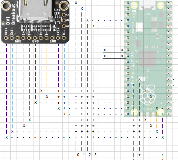
I connected the HDMI module according to this plan  sorry, I just had Excel to draw the design and ignore the other lines Edited 2024-11-19 05:14 by Martin H. 'no comment |
||||
| Mixtel90 Guru Joined: 05/10/2019 Location: United KingdomPosts: 6757 |
TX2+ = D2+ TX2- = D2- 1+ = D1+ 1- = D1- 0+ = D0+ 0- = D0- TXC+ = CK+ TC- = CK- You should also connect "5" to 5V. You'll also need GND, of course. Mick Zilog Inside! nascom.info for Nascom & Gemini Preliminary MMBasic docs & my PCB designs |
||||
| stanleyella Guru Joined: 25/06/2022 Location: United KingdomPosts: 2108 |
Thanks Martin and Mick. great help for me. I got one pico2 2350 left from 4 and stripboard a hdmi usb mmbasic compatible with sd card reader and audio. The olimex board was too good to be true. |
||||
| stanleyella Guru Joined: 25/06/2022 Location: United KingdomPosts: 2108 |
If I use this from the manual config suggestion and works vga usb OPTION SERIAL CONSOLE COM2,GP8,GP9 OPTION SDCARD GP13, GP10, GP11, GP12 OPTION AUDIO GP0,GP1', ON PWM CHANNEL 0 Gp14=pin19 Gp15=pin20 Gp16=pin21 Gp17=pin22 Gp18=pin24 Gp19=pin25 Gp20=pin26 Gp21=pin27 would OPTION HDMI PINS 19, 21, 26, 24 work or I got it wrong? |
||||