
|

|
Forum Index : Microcontroller and PC projects : Growing a Maximite - Part 2
| Author | Message | ||||
| paceman Guru Joined: 07/10/2011 Location: AustraliaPosts: 1329 |
This is a continuation of Mobi's thread Growing a Maximite The original thread was getting pretty long and this post is more of a 'how to'. ------------ Hi David and all, Well I finally got brave and used one of my virgin $10, 100 pin, 0.5mm chips (PIC32MX795F512L-801PT) from MicroChip to ‘grow’ a Colour Maximite (CMM) on a break-out-board (BOB) I bought. This BOB can be used to make a CMM or alternately it can be used as a ‘generic’ PIC32 giving access to all pins. I wanted to be able to use it in both those modes so that I could use it in CMM projects and also use it for loading some stand-alone learner hex files compiled from C code via my PICkit 3. I’ve bought Lucio de Jasio’s book that Geoff recommends (Programming 32-bit Microcontrollers in C – Exploring the PIC32). The book’s basically a start-from-scratch lesson in C for the PIC32 using the MicroChip’s free MPLAB IDE and C compiler. A lot of the example code assumes though that there is access to any of the PIC32 pins, i.e. a ‘generic’ PIC32 which is not the case if the chip is hardwired as a CMM. To be able to swap between the two ‘modes’ I’ve made it so that any ‘non-generic’ connections required to use it as a CMM are done on a separate proto board e.g. the I/O connections for USB and VGA, or, in a couple of cases as mods with linkable pins added to the BOB. The Break-out Board and Mods. This BOB is made by ETTEAM (www.ETTEAM.com) in Thailand, as is Mobi’s board, and available for about $2 from several places, e.g.Break-out board It’s a bit different from the board Mobi sourced from Futurlec in that it has connections and pads for the support components in SMD format underneath, which I think is pretty handy, and there’s also an ICSP header provided to program it. Here’s how it looks on arrival. 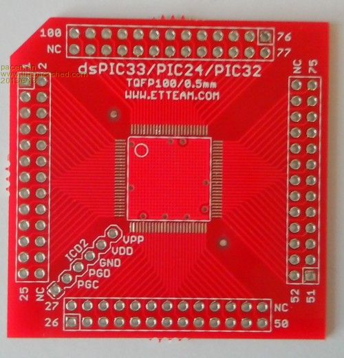
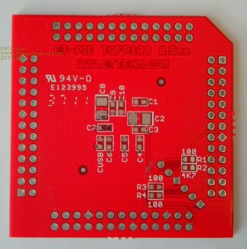
As you can see it has the values for the resistors marked, but not for the capacitors – very helpful, and I couldn’t find any documentation on the ETTEAM site. I Googled around a bit and found this blog PIC32 BOB which also has a link to a schematic giving all the capacitor and resistor values – they’re probably standard off the chip documentation but I wasn’t keen to read through that – yet! From what I can make out it’s pretty much as Geoff has used for the CMM but there are a couple of ‘gotcha’s’ in the connections – more on that below. The infamous 10uF capacitor on the Vcap line is shown as a ‘normal’ tantalum and for that I used a 1206 format 6.3v Jaycar cap I had on hand (P/N RZ6541) which so far has worked fine, although I am a little nervous about the 6.3v limit. I now have some of the low ESR ceramic caps Geoff recommended so if there’s a problem that’ll be the first thing I change! Here’s how the BOB looked after I soldered in the PIC, the support SMD’s, the header pins and my mods. 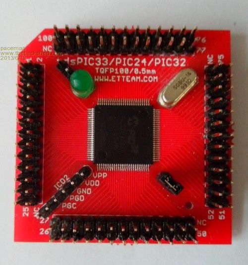
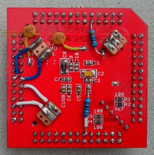
Soldering the PIC wasn’t as bad as I thought it would be. Geoff has directions on his website for this and so do several others on YouTube so I won’t repeat it. The SMD resistors and caps I’d previously sourced from Rockby for pretty reasonable prices (around $3 to $5 in 100 or 10 quantities for resistors and caps respectively) but you can also get them in multi value packs from eBay for $10 or so, e.g. SMD packs When you’re doing the soldering you definitely need a lighted magnifying system of some sort. I have a small stereo microscope that works well but I think one of the large-ish diameter magnifiers with in-built LED’s would be a good option too and a lot cheaper. No doubt you’ve noticed some ‘extras’ on the BOB. These components/connections were added using through-hole components. I drilled through the BOB along the diagonals (where there weren’t any top tracks) using a little “pencil’ hand drill and a small piece of proto board as a 0.1” spacing guide. The drill diameter was selected to give a close fit for header pins. On the bottom the drilling goes through the copper of the Vss (Gnd) plane grid so clearance was made by trimming around the holes with a sharp Stanley knife – a bit finicky! I super-glued small pieces of proto board under the BOB in line with the holes to make the connections and to give a solid base to the header pins inserted from the top – thinner proto board than the 1.6mm I had would have been handy here. These headers then allow for links needed to maintain the ‘generic’ mode in a couple of circumstances, as below. The mods made were: 1. Adding the 8MHz crystal and caps – a permanent mod. The Vss (Gnd) connection of the two 22pF caps was made directly to the Vss plane at the back of the BOB by scraping away a small area of solder mask. 2. Adding a linkable connection between Vusb (pin 55) and Vdd (3.3v) at pin 62*. This link needs to be in when used as a CMM and for probably most other situations, but it will need removing in some ‘generic’ cases. 3. Adding the 10 ohm resistor between AVdd (pin 30) and Vdd (3.3v) at pin 37*. Currently I’ve hardwired this as a permanent mod but it shouldn’t be for ‘generic’ use. I figured I was unlikely to want to use an external voltage reference for a while at least - but then you never know… This mod was a bit tricky because AVdd needed to be picked up at the PIC32 end of C4. Luckily there’s a via going to C4 at that point which made poking a very short resistor lead into it possible - but I did need to scrape away a tiny area of solder mask to get a good connection. 4. Adding an LED with current limiting resistor (330 ohm) that can be jumpered to any pin and the ‘other’ end to Vdd or Vss. I’ve currently got the LED hardwired as per the CMM, pin 93 and 3.3v, but to keep the ‘generic’ capability the LED needs to be controllable by other pins and in both current source or sink mode i.e. the ‘other’ end connected to 3.3v or Gnd. *Note: The connections to Vdd (3.3v) noted in points 2 and 3 don’t have to be made to those particular Vdd pins, any Vdd pin will work, they were just closest. It would probably be better to connect them to the Vdd power plane but unfortunately that’s not possible because it’s inaccessible under the PIC32 chip. The I/O Board – USB & VGA (so far). The next adventure was trying to make a neat-ish I/O board for the CMM USB and VGA connections broken out with pins to jumper to the PIC board. I was trying to keep it reasonably compact so that I could later put an SD card reader behind the other connectors – yet to do. Here’s what I ended up with. 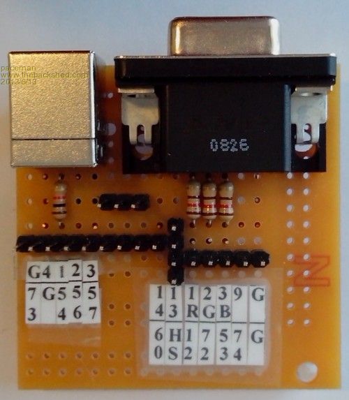
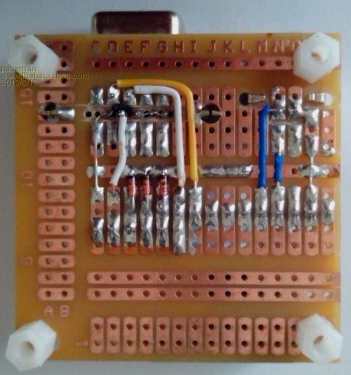
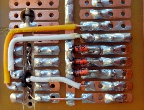
I’ve included a magnified photo to show how I soldered the VGA pin diodes and the series of Gnd connections on the VGA connector. These ground connections were finicky. First I had to drill holes between five of the normal proto board holes to accommodate the offset second row of the VGA pins i.e. pins 6 to 10. Then pins 5,6,7,8,&10 needed to be connected to Gnd but pin 9 (the composite select pin) had to be kept insulated. To do this I cut a V section out of the proto board along the offset middle VGA row. This electrically separated all three rows of the connector and then I looped some bare wire-wrap wire (it had to be fine) along the ground pins at the base of the ‘V’. I threaded a very small length of insulation (off some hookup wire) along this wire to pin 9 to maintain its insulation before I soldered the fine wire to the Gnd pins. I hope that all made sense – in the end it might have been easier to do what Mobi did and etch up a proper board - except that I’ve yet to get into etching boards. I mulled over how to connect the four pins 77, 69, 47 & 14 for the CMM VGA horizontal sync, but still be able to use the BOB in ‘generic’ mode with them un-connected. In the end I settled on connecting them at the I/O board. I wasn’t confident this would work but amazingly it did. Those pins can be seen aligned vertically to the other jumper pins in the ‘top’ photo above. Installing MPLAB X and loading the bootstrapped MMBasic. The next step was to download MPLAB X from the MicroChip site and install it on my Win XP notebook. MPLAB X is MicroChip’s replacement for MPLAB IDE and it downloaded and installed without problems. The latest CMM MMBasic hex file containing the bootloader (V4.1) from Geoff’s website was then also downloaded. Next I jumpered up the USB connections as shown below, plugged the PICkit 3 into the notebook, (driver previously installed) and fired up MPLAB X. After a couple of false starts all the messages told me everything had loaded up OK and up came the power LED – success! 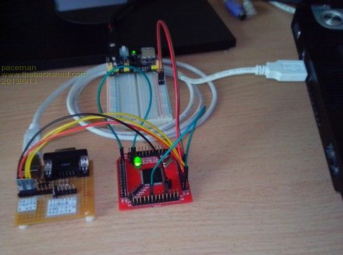
Actually that’s not quite true; at first the MPLAB X messages all came up saying it had loaded properly, but the LED just blinked and then turned off. I investigated and found I had correctly connected the LED as given in the BOB blog schematic, but with their choice of active pin, pin 1 (RG15) swapped to the Maximite power pin standard, pin 93 (RE0). Unfortunately though, their pin is sourcing current with the other end connected to Gnd, which I’d duly done. The Maximite’s power pin though is sinking current with the other end going to 3.3v. I changed it to that, made sure the LED was forward biased, re-powered it without the PICkit 3 and lo… the LED stayed on. Just to prove I wasn’t dreaming I launched Tassy Jim’s trusty MMEdit program and up came the MMBasic splash screen. Running USB and VGA and composite. The photos below show firstly the setup for VGA and USB together (jumpering getting a bit busy) and then the whole thing running Geoff’s demo COLOUR-1 program. I fed the VGA output of the BOB to a $12 VGA to Video converter and then the converter’s VGA and composite outputs concurrently to a Dell VGA screen and a small $25 composite screen. 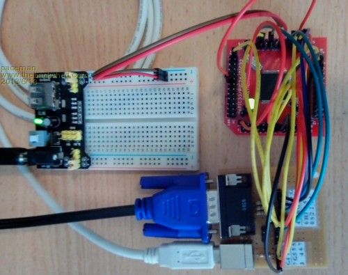
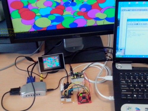
All this shows, as Mobi has also done, that you can have a full 100 pin ‘generic’ PIC32 on a break-out board for ‘training’ and still be able to convert that to and from a Colour Maximite configuration. Now for the SD card, the clock and a 3.3v supply – I reckon they might fit on the I/O board with a bit of juggling. Greg |
||||
MicroBlocks Guru Joined: 12/05/2012 Location: ThailandPosts: 2209 |
Greg, that is a fantastic write up! And a great result. As you maybe know i am busy designing 'blocks'. The PIC32 MCU 'block' will be smaller then the one from ETTeam but the idea is the same. My biggest decision i now have to make is which connectors should i use. The idea is to have square 'blocks' that contain the circuitry and have connectors on the top side. When connecting these 'blocks' my first idea was to use female headers so that you can use male-male cables to connect them and also use the same male-male cables to connect to a breadboard. I see that you used the male headers and use female-female cables. Was that for a particular reason, or was it what you had available? Using what you have is always good. In my case i will need to order and would like your opinion which would be better. I think that the male header pins are all open and therefore for less careful people or ones that are starting there is a danger of shorting them inadvertently. I need to make my 'blocks' as fool-proof as possible and thought the female headers would help with that. However if availability or usability is better with male headers i can weigh that in my decision. For the female headers there are two types, the normal ones from the same series as your male ones, or the sip line. I am finalizing my design and would appreciate some feedback on this 'dilemma'. I will need to make a decision about those connectors pretty soon. Below is an example of the power 'Block' to get an idea how they will look like. Others like port expanders, digital potentiometers, 7-segment, wifi are also almost done, a few more like EEPROM/RAM/FRAM, servo control, keyboard, bluetooth, RTC, RFID, Joystick, steppermotor, battery pack etc are on the drawing table. It will all be open hard/software and contributions and ideas are very welcome. Most of the communication will be with I2C. This is the topside of a PCB, components will be on the bottom side to protect them from damage. These PCBs will then function as a 'lid' for a small box made from plastic or aluminum for a deluxe more sturdy version. 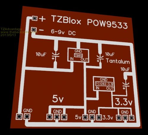
The special idea behind it is that once you have made a working project out of those 'blocks' you would then be able to order a pcb with all the circuitry on it, wired exactly as it is done on the prototype and have a end product that is worthy enough to be showed and sold and freeing up the 'blocks' for the next project. Microblocks. Build with logic. |
||||
bigmik Guru Joined: 20/06/2011 Location: AustraliaPosts: 2914 |
TZ, Greg, Yes I second that.. TZ, I generally chose MALE Pins for PCB connections and use female cables this is twofold, 1. Less likely to inadvertantly short to the wrong pin/other components if `hot plugging' 2. If the female `wears out' through excessive use it is easier to replace a cable than desolder a female socket. The above is assuming the boards dont `stack' If stackable obviously one is male the other female. Regards, Mick Mick's uMite Stuff can be found >>> HERE (Kindly hosted by Dontronics) <<< |
||||
MicroBlocks Guru Joined: 12/05/2012 Location: ThailandPosts: 2209 |
Mick, Those are two very good points. Especially nr2. Male pins are indeed more robust and cables are cheap and easy to replace. Thanks for that insight. ETTeam is 100m from where i live. :) They have lots of good stuff. Microblocks. Build with logic. |
||||
| MOBI Guru Joined: 02/12/2012 Location: AustraliaPosts: 819 |
Well done Greg. I'm impressed. The BOB I used was unfortunately a generic TQFP 0.5 / 0.4 mm type without the component pads for power etc. That just meant a lot more hand wiring with "little blue wires" as downwind calls them. That is the kynar wire-wrap stuff. I find it does a much better job than the standard "hookup" wire. In my first version, I used female headers but found that they were too prone to pulling out so swapped to male pins using the Dupont style jumper leads. They tend not to let go easily. My second version has all the I/o devices (SD,USB etc + the xtal) in a row on one piece of PCB also with male headers. I'll do a photo or two when I get it etched. I use express PCB which doesn't have library footprints for things like VGA connectors so I had to create them. Not too difficult. I had trouble getting the SD card to be recognised and ended up jumpering the card detect pin to ground on the BOB. Not all SD cards holders have the same foot print particularly they way they handle write protect and card detect. I also found that it is not a good idea to have a 12v power supply on the bench as well as a 3.3v power supply. The pic makes a funny hissy noise as the magic smoke escapes when you plug in the wrong one!!!! Ouch!! I've got to go to Canberra in a couple of days so won't be able to progress more for a week or so. BTW, has any one used the MPLAB X IPE with the pickit3 instead of MPLAB X IDE ? I use the IPE as it just does the firmware programming and seems to work quite well with the PIC32 and remembers the previous set up. A future plan I have for the generic MM is to include some Fast Fourier Transform capability to enable audio spectrum analysis and logging. A bit ambitious but most of the C code is "out there". We'll see.  At the moment, I can display the infra sound spectrum using a Bessel filter with the SilChip Pre/Champ config. At the moment, I can display the infra sound spectrum using a Bessel filter with the SilChip Pre/Champ config.David M. |
||||
| paceman Guru Joined: 07/10/2011 Location: AustraliaPosts: 1329 |
Thanks for your comments TZ. It's certainly a lot more convenient using a 'full' CMM (mine's a CGCMM) for MMBasic program development and for connecting standard CMM peripherals or breadboard circuitry on a one-off basis, and that is what I mostly do, but you can't keep adding them stand-alone to different projects. Also the other connections compromise using them 'generically' as I wanted to for learning purposes. I kicked around the male/female connector problem for some time as well. In the end I went with the male because I thought I might be probing pins a bit with test gear and that would be a lot easier with the male pins. I've also armed myself with M/M, F/F and M/F jumpers and all those combinations are needed at various times. My last couple of 'buys' were the ones they offer in wide rainbow cable with each conductor terminated. That way you can tear off single or multiple jumpers as needed and they're pretty cheap. I think sometimes too if you were using one of these BOB's permanently in a project that projecting the pins the other way i.e. out of the bottom of the board could be useful because you could insert them into female connectors or even directly solder them with pins to matching holes in a board below. The 'footprint' of the whole 100 pin layout could be added as another 'component' to a board layout program, but only the pins needed would have tracks connected to them. The area under the BOB could include any 'standard' peripherals wanted e.g. the clock, Xtal, 10 ohm resistor, Vusb connection (or not) etc - although you'd need longer 'stacker' pins probably in that case. That sounds pretty comprehensive all right and the example looks rather 'groovy' - you deserve to go well with it. Greg |
||||
| paceman Guru Joined: 07/10/2011 Location: AustraliaPosts: 1329 |
Thanks David, you inspired me! Yes the Kynar is easier but I worry a bit it might 'catch' occasionally and break connections; once you've bent the hook up wire to the right shape it stays down neatly on the board even if it's a b....r to get right - maybe I'm paranoid. Re the male connectors - yes I agree, also see my comments back to TZ. You could probably add a little 3.3v supply to your new I/O as well  . It'd be totally stand-alone then (connected to USB or something of course!). . It'd be totally stand-alone then (connected to USB or something of course!).
I've installed DipTrace and had a bit of a play but I think a 'bit-of-a-play' doesn't cut it for board layouts and schematics - more learning, but all part of the grand scheme of things! Hmmmm.. I bought a couple of these SD module thinking I might be able to use them with a few mods - there are no active devices on them. If not, well at that price nothing lost. Probably poor quality electrolyte. Not me yet but after reading a bit of the info they give it's probably an easy way to go. It's a pity they don't mention about IPE when you're installing MPLAB X, it would have eased my mind. I wondered whether it was just some crap-ware and whether I should stop it installing. Mind you, using MPLAB X is very easy so I'm not sure it's worthwhile even hanging onto it. Wow, pretty ambitious, you're certainly not going to do that with MMBasic. I should have had you around in my X-ray diffraction days! Just a thought - I reckon you'd eat an ESR/cap meter 
Greg |
||||
| paceman Guru Joined: 07/10/2011 Location: AustraliaPosts: 1329 |
Thanks Mick, pity I can't do your quality of photos - maybe it's because I'm reducing them to 500 pixels wide before I upload them - they looked OK when I took them. Re the male/female connectors - yes I agree with your comments, I'd also add that probing with test gear is much easier with pins. I've given that feedback to TZ too. Greg |
||||
| MOBI Guru Joined: 02/12/2012 Location: AustraliaPosts: 819 |
I have given quite a bit of thought to the MM ESR tester and keep getting stuck at AtoD fast enough to read the value of the appropriate part of the pulses. I think that is on another thread to pursue some time. The SD board you linked to - I have one but have not used it yet. I think the only active component is the +5v to 3.3v Vreg chip. Just looking at the board, I can't see any facility for card detect or write protect. Looks like a jumper or two on the BOB. I've never had a problem with the kynar wire and always found it quite flexible. The main thing I like about it is that it is quite thin and takes up very little room and doesn't seem to shrink back when heated. Stripping can be a bit of a problem but a good pistol type stripper works well. I've installed DipTrace and had a bit of a play but I think a 'bit-of-a-play' doesn't cut it for board layouts and schematics - more learning, but all part of the grand scheme of things! I have a 3.3v supply hooked to my main BOB unit - it was a fore-runner that only had a round DC connector that copped the wrong voltage. Learning is what this whole MCU bit is about for me. If I actually used all the projects I make, I would have been stuck back on an earlier one long ago. David M. |
||||
MicroBlocks Guru Joined: 12/05/2012 Location: ThailandPosts: 2209 |
Thanks guys for the feedback about female or male pins. The conclusion is clear that male connectors are better because: 1. Less likely to inadvertently short to the wrong pin/other components if `hot plugging' 2. If the female `wears out' through excessive use it is easier to replace a cable than desolder a female socket. 3. male cables are too prone to pulling out 4. probing pins with test gear is a lot easier All very useful information as my personal experience is more with breadboards and female connectors. @Greg The pictures you upload have the typical compression artifacts, i think the compression rate is too high. Making them 500px wide is not the problem it is how you save that file. I don't know which program you use but in many you have a 'slider' or other way to specify how much compression you want. Best compression = worst picture. And i think the forum software also does some processing on it, like adding a watermark. The artifacts and lower quality can also be caused by this. If someone wants some help or tips with making a schematic, footprints, etc in Diptrace just ask. :) Maybe we can share library and footprints. I am currently organizing my files so that i can put them online to share. Microblocks. Build with logic. |
||||
| paceman Guru Joined: 07/10/2011 Location: AustraliaPosts: 1329 |
And i think the forum software also does some processing on it, like adding a watermark. The artifacts and lower quality can also be caused by this. That's a distinct possibility. The photos started out as 340KB .jpg files from my new Aldi Android V4.1 smartphone, 2560x1920, 4.9M pixels - all that off image information off my phone. I processed them using Arcsoft's PhotoStudio V5.5 that was originally loaded with my Canon camera software. First I cropped them a bit, maybe 20%, then using their 'View' tab and 'Image size' which I set at 500 pixels horizontal (as suggested in Glenn's TBS 'Forum Settings' and then GO. It automatically stores the processed file back in the folder as a .jpg at the 500 pixel size and that's what I've uploaded to TBS. The files being uploaded are only around 70KB which are pretty small given they started at 340KB. Any comments that could improve things greatly appreciated. Greg |
||||
bigmik Guru Joined: 20/06/2011 Location: AustraliaPosts: 2914 |
Thanks Mick, pity I can't do your quality of photos - maybe it's because I'm reducing them to 500 pixels wide before I upload them - Thanks Greg, I'm glad that they are appreciated.. Yours are fine anyway... As per my Pictures.. I think as TZ said that Resolution is one thing but QUALITY is another.. I use Photoshop CS5 for my editting and when I save my image as a JPEG (my preference) there is a slider for quality setting and it shows the size that the file will be when saved at that setting... I usually use as high a setting as possible that keeps the picture size below the 1MB max size that TBS requires (usually 500kB .. For Information most (if not ALL of my pics are taken using my HTC (mid range not high end) phone's 5M camera, I crop to show the section I wish to show and then save and recheck before I post it... The way TBS reduces the image again can be quite annoying as well.. If I need to show more detail (like a schematic) I save it as a PDF first. Regards, Mick Mick's uMite Stuff can be found >>> HERE (Kindly hosted by Dontronics) <<< |
||||
| paceman Guru Joined: 07/10/2011 Location: AustraliaPosts: 1329 |
Thanks Mick, I'll have a bit of a play and see if I can't improve things. The photos look good on the Aldi phone screen (4.5") and the phone does a surprisingly good job of focussing at very close to the subject, e.g. around 12cms. I thought maybe I was shaking it a bit but then if they're good on the phone screen that can't be the case. I find getting the lighting right is also one of the biggest problems. I need my old Zeiss UltraPhot 2 metallurgical microscope that I used to use 35 years ago - but that ain't gonna happen - it was worth about $15,000 in 1970! Check me out below - OK, OK it was the '70's 
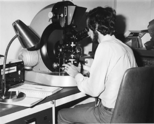
Hey, I think that's better already - I didn't reduce it so much, 800 instead of 500 wide and the file size was 110K or thereabout instead of 70K. Greg |
||||
bigmik Guru Joined: 20/06/2011 Location: AustraliaPosts: 2914 |
Hi Greg, That picture looks OK, but who is the leprechaun in the photo? 
Sorry I couldn't resist... If I had some equivalent photo of me I would post it back for you to throw a brickbat back. Regards, Mick Mick's uMite Stuff can be found >>> HERE (Kindly hosted by Dontronics) <<< |
||||
James_From_Canb Senior Member Joined: 19/06/2011 Location: AustraliaPosts: 265 |
Check out the prices on eBay for metallurgical microscopes. They've dropped a bit :) As a bonus, it looks as though they'll plug straight into a laptop. That might be overkill if all you're only after better focus and lighting though. James My mind is aglow with whirling, transient nodes of thought careening through a cosmic vapor of invention. Hedley Lamarr, Blazing Saddles (1974) |
||||
| paceman Guru Joined: 07/10/2011 Location: AustraliaPosts: 1329 |

 People used to say I looked like Abe Lincoln! - they haven't mentioned that for a while though come to think of it. People used to say I looked like Abe Lincoln! - they haven't mentioned that for a while though come to think of it.
James - yes, the prices are incredibly low, considering that they're pretty high precision things - I don't know how the manufacturers could make a buck now. I guess though there are squillions of them used in electronic manufacturing now which wasn't the case back then. That big Zeiss was state-of-the-art back then - it had everything, motorised micro-hardness testing, phase contrast, interference contrast, dark field, top lighting options for macro work, cameras - 35mm, 120mm, 4x5, Polaroid (remember that) - it even had fibre optics (back then) for difficult lighting, Xenon lamps you name it - but I digress! Greg |
||||
bigmik Guru Joined: 20/06/2011 Location: AustraliaPosts: 2914 |
 Yes! I remember, I have had a beard since About 1972/3 (Since I was able to grow one) Now, 40+ years later I still have one, albeit a rather faded version of yesteryear... In fact I have shaved it off probably only 6 or 7 times since I could grow a proper beard (`bum fluff' excluded from that) Here I am about the late 1980's at one of the (then) regular Friday night drinking and PC fixing/designing episodes where I would drink Don's beer and breath in about a packet of Don's Cigarettes (2nd hand smoke, as I was/am a non smoker). 
Regards, Mick Mick's uMite Stuff can be found >>> HERE (Kindly hosted by Dontronics) <<< |
||||
MicroBlocks Guru Joined: 12/05/2012 Location: ThailandPosts: 2209 |
I started with a TRS80 Model I that a colleague of my uncle had who tought me how to use it. He had a beard of course. :) I was 13 at the time, so i was without one. Later when i got my first projects and go meet the 'technical' or 'programmer' guy they always had a beard. And they were really the ones with the knowledge, the rest.. ah well... Still at around 18, no beard of my own as it did not want to grow. After a few more tries i gave up. :) I was determined to become an expert anyway, but still without a beard it is hard to say if i succeeded. The picture is somehow not complete. Now my wife stops me from growing one as she says it makes me look old. Mmm i guess that is a good thing. Looking back i realize that i have learned the most from those guys and somehow the beardy types were always calm, patient and friendly. BTW, i love it when threads on this board go completely off topic and are not removed by a moderator. Microblocks. Build with logic. |
||||
bigmik Guru Joined: 20/06/2011 Location: AustraliaPosts: 2914 |
BTW, i love it when threads on this board go completely off topic and are not removed by a moderator. TZ, Maybe we should rename this thread to `Growing a Beard'? 
Its not entirely Off-Topic as I did mention repairing/designing PCs (in those days of course they were Z80 based TRS-80, System80, and an Excalibur 64. Don and I used to sit around and repair Excalibur 64's that didnt work that the factory's (yes Australian based in those days) own engineers could not repair, mind you these were kits and were built by users who, in many cases, couldn't solder to save their lives... Maybe they had great gardens though... Don had designed (or was that Rob McAllister, Don?) a STATIC Z80 which we could set up addresses and single step through Rom/Ram to check address decodes and find out why the Z80 wasnt ticking along... In those days CPUs were a lot simpler than today's VLSI beasties.. You couldn't single step a Pic32 with all the complex timers and interrupts etc. Regards, Mick Mick's uMite Stuff can be found >>> HERE (Kindly hosted by Dontronics) <<< |
||||
| paceman Guru Joined: 07/10/2011 Location: AustraliaPosts: 1329 |
Like TZ says Mick - you look calm, patient and friendly. probably something to do with what's in front of you! I got married in '72 with a beard I'd already had a couple of years - the girls obviously liked them. Back on topic again from me - that Olimex I/O board that Don sells is a brilliant price at a bit less than $7. Do you reckon that could be modded reasonably easily to replace the one I made (this thread). I know its for a mono Maximita, not colour but maybe with a couple extra connections? Greg |
||||