|

|
Forum Index : Microcontroller and PC projects : Colour MM schematic
| Author | Message | ||||
| MOBI Guru Joined: 02/12/2012 Location: AustraliaPosts: 819 |
I have found a schematic for Colour MM V1 which doesn't seem to show CAN facilities etc. Is there an up to date schematic somewhere and I have managed to overlook it? David M. |
||||
| MOBI Guru Joined: 02/12/2012 Location: AustraliaPosts: 819 |
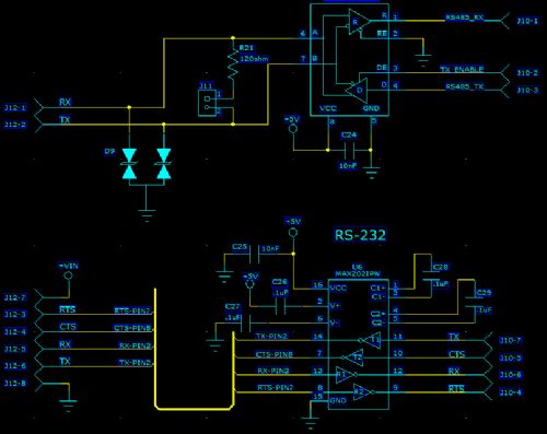
I have pretty well worked out what I wanted, however, a schematic of the RS232/485 wouldn't go astray. My eyes aren't as good as they used to be and I imagined that the serial interface circuit at the edqe of the sea of holes was connected to the pic in some way until I found the serial example on the Blogspot. I guess the circuit was done that way so that either comm port can be afforded an onboard interface. (who would want more than one RS232 normally?) I still think that a simple schematic would have made following the description of the hookup a lot easier to follow. Is there a connection description for RS485 as well? David M. |
||||
CircuitGizmos Guru Joined: 08/09/2011 Location: United StatesPosts: 1425 |
This is for the CGCOLORMAX1: 
Micromites and Maximites! - Beginning Maximite |
||||
CircuitGizmos Guru Joined: 08/09/2011 Location: United StatesPosts: 1425 |
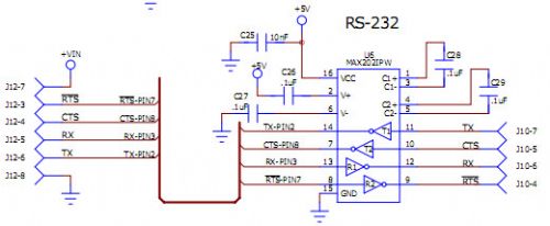
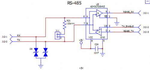
Well that isn't the best image capture, is it? On the CGCOLORMAX1 both the RS232 and RS485 circuits are stand-alone. Not connected to the signals on the microcontroller. Because there are two drivers and two receivers on the RS232 circuit, you can support two simultaneous RS232 channels (no handshaking) using RTS for RX and CTS for TX. Micromites and Maximites! - Beginning Maximite |
||||
| MOBI Guru Joined: 02/12/2012 Location: AustraliaPosts: 819 |
Thanks for the schematic, it is just the cat's whisker. I can live with the appearance of the drawing - its the info that counts. I suspected one of the chips was a max232 but eyesight not good enough to read the fine print. I never (but should have) thought of using cts and rts for the tx and rx signals. Thanks again. David M. |
||||
bigmik Guru Joined: 20/06/2011 Location: AustraliaPosts: 2914 |
Hi All, Until a schematic is available that is better than the picture above I have tried to enhance it to be easier to view. (downloadable PDF) Hopefully it helps someone Regards, Mick 2013-01-16_223802_ColormaxComms.pdf Mick's uMite Stuff can be found >>> HERE (Kindly hosted by Dontronics) <<< |
||||
| MOBI Guru Joined: 02/12/2012 Location: AustraliaPosts: 819 |
Thanks Mick. It is a better copy than the one I did. I did a screen dump to Paint, made it a bit bigger and ended up with a Blueprint (Blackprint???) Didn't look to see if I could reverse colours. Anyway, I now have something useful to put in my Maximite/PIC32 clip folder - yet another one for the already over crowded bookshelf. Surely there is an up to date schematic of the various versions of Maxi? Or is it "copyright"? Mind you, I know of a few people who design things without doing a schematic and rely on the PCB layout. David M. |
||||
CircuitGizmos Guru Joined: 08/09/2011 Location: United StatesPosts: 1425 |


Micromites and Maximites! - Beginning Maximite |
||||