|

|
Forum Index : Microcontroller and PC projects : 4x4 Matrix board with one analogue input
| Author | Message | ||||
| paceman Guru Joined: 07/10/2011 Location: AustraliaPosts: 1329 |
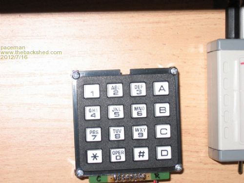
Jez Siddons documented a single analogue input implementation of a 4x3 keypad a few months ago. See the re-posting of it on this forum at: 4x3 Keypad implementation. I decided to try Jez's technique but using a 4x4 keypad to allow some spare keys to use for other functions e.g. menu, delete, navigate etc. The physical setup is shown below and the keypad is a $29 version from Jaycar (I'm sure there are plenty of others available for a lot less than that though). 
I had to change Jez's analogue "board" resistances and the constant current setting of the LM334Z constant current device to obtain good spread for all 16 keys across the 3.3v available to be read by the Maximite. Supply voltage for the keypad needs to be 5v as used for the 4x3 keypads. The resistors used were 1K,2K,3K,4K for the columns and zero,4K,8K,12K for the rows, giving a 1K to 16K matrix in 1K steps (nice and simple). Some of the resistors are non-standard values but all were in stock at Rockby and delivered in two days. The LM334Z constant current source ($1.50 or thereabouts from Jaycar) was set at 0.190mV (actually 0.189) using 680 ohm & 6K8 ohm resistors, maintaining the 1:10 resistance ratio recommended in the National Semiconductor datasheet to obtain minimal temperature dependance. I didn't have a 1N457 diode (as recommended by NS) so substituted a 1N4148 which seems to work well. (Incidentally, Jez's schematic shows a 1N547A which I think is probably a typo.) The analogue parts were soldered to a small piece of proto board which can be seen in the second photo. The header holes on the keypad board were connected to the proto board with a short piece of 16 conductor ribbon cable (every second conductor is at 0.1" spacing which gives a neat connection). Ground, 5.0v supply and analogue signal out, were connected using a 3 pin right-angle male polarised connector which is convenient to connect to female jumper wires and then later to a permanent plug for a project. The proto board was attached to the keypad with two short M3 screws which screwed to 5mm lengths of threaded plastic standoff Super-glued to the keypad board. Instead of using Jez's V=IR type calculation to determine which key was pressed I used a simple linear calibration of key "number" against the voltage read by MMBasic as shown below. The conversion to integer (for the key number) provides a reliable conversion of voltage to the key number without needing to implement ranges etc. It is also easily re-calibrated. Char Ohms Key No Volts Diff 1 1 1 0.171 2 2 2 0.367 0.196 3 3 3 0.558 0.191 C 4 4 0.750 0.192 4 5 5 0.940 0.190 5 6 6 1.134 0.194 6 7 7 1.328 0.194 B 8 8 1.518 0.190 7 9 9 1.708 0.190 8 10 10 1.903 0.195 9 11 11 2.094 0.191 C 12 12 2.288 0.194 * 13 13 2.452 0.164 0 14 14 2.645 0.193 # 15 15 2.838 0.193 D 16 16 3.029 0.191 Linear Calibration: KeyNo(Y) = 5.2539(X)Volts + 0.0534 R squared = 0.9999 (very good linear fit) Set Current = 0.189mA Supply Volts = 5v R1 = 680 ohms R2 = 6.8K ohms Nokey=3.29678v - equiv to Key No 17, i.e. 'x' in padded keymap) ------------------------------------------------------------ --------- The MMBasic program written by Jez Siddons was modified and is given below. ------------------------------------------------------------ --------- '4x4 Keypad Using One Analogue Input 'MMBasic V3.2C (original by Jez Siddons) 'Modified by Greg Yaxley) Cls SetPin 1,1 'Pin 1 is analogue input SetTick 10,timer_int '"timer_int" samples the keypad voltage every 10mS via Pin 1 'and converts it to the mapped keyboard character. 'Only keys generating 2 consecutively same characters are 'considered valid. 'Jitter, bounce & errors are eliminated. 'Valid keypresses are put into keypress$ keypattern$="123A456B789C*0#Dxxx" '"Keypattern$" maps the keyboard characters in increasing 'resistance order. It is padded with xxx to return x when 'keys are OFF, i.e. none being pressed. "No keys pressed" is 'the lowest resistance & thus highest voltage condition. Do If keypress$<>"" Then 'This variable is set by a press on the keypad Print keypress$; 'Print the keypress on the screen keypress$="" 'Clear that keypress, ready for next one. EndIf Loop Until Inkey$<>"" 'Loop till a character is entered (on the console) timer_int: vkey=Pin(1) 'Read pin(1); voltage from keypad keynum=Cint(5.2539*vkey+0.0534) 'Convert to integer by calib'n eqn keyhist$=Right$("xxxx"+keyhist$+Mid$(keypattern$,keynum,1),4 ) If Right$(keyhist$,3)="xxx" Then keyoff=1 If keyoff=1 And Mid$(keyhist$,3,1)<>"x" And Mid$(keyhist$,4,1)<>"x" Then If Mid$(keyhist$,3,1) = Mid$(keyhist$,4,1) Then keypress$ = Right$(keyhist$,1) keyoff=0 EndIf EndIf IReturn 'Back to main input do loop ---- ------------------------------------------------------------ ------- This all seems to work quite quickly and, so far at least, very reliably. I have also now just finished hooking it up to the little Nokia 5110 84x48 graphics display mentioned in other threads. This now displays a running clock, parameter input from the 4x4 Keypad with "backspacing" of input and a blinking, positioned cursor. I'll share that with everybody hopefully before too long. Greg |
||||