
|

|
Forum Index : Microcontroller and PC projects : Test-A-Mite MM/DM GPIO Tester
| Author | Message | ||||
bigmik Guru Joined: 20/06/2011 Location: AustraliaPosts: 2914 |
Hi All, I have designed a tester PCB (called Test-A-Mite) that will put the MM/DM through its paces and test the following features are working correctly on our `mites. Analog Input Digital Input & Output Frequency Input Period Input Count Input It also has a few LED Demo routines for Fun and lets face it who doesnt like fun.. Fun LED chases as follows: Simple LED Chase LED Bar Graph Display LED Cross Over Binary Counting All information can be found HERE including some short video clips of a DM mini connected to the Test-A-Mite doing each of the Fun LED chases The schematic and part list is all available above so it is not too hard to make your own or PCBs are available from Dontronics for around $6ea. or $8ea including World wide Postage LETTER 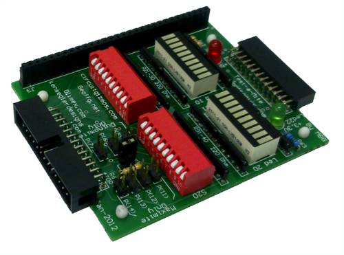
Mick's uMite Stuff can be found >>> HERE (Kindly hosted by Dontronics) <<< |
||||
| paceman Guru Joined: 07/10/2011 Location: AustraliaPosts: 1329 |
Hi bigmik, Just for a contrast to your very neat board - here's my kludge. 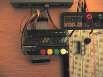
I did it a few months ago using one of Dontronics old SimmStick DT203 boards. One advantage is the LED's have Darlington drivers so don't load down the PIC. There's no neat IDC connection unfortunately as you can see but it is pretty flexible. BTW - how do you make your nice photos? Greg |
||||
bigmik Guru Joined: 20/06/2011 Location: AustraliaPosts: 2914 |
Hi Greg, I think I remember you doing that in the discussion that started me on the path of the Test-A-Mite, (I think I designed the DT203 for Don, Not sure now.... if I did it will have MBG on it some where) The picture, believe it or not, was via my mobile phone (cheapo nokia E72), I placed the TAM on a bit of white paper, took the shot (close up and flash on) then photo shopped the cream colored paper to White and contrast enhanced.. The TAM also tests Robs CGMMSTICK1 (via the 30 pin header on the top, (as shown in the picture above) Regards, Mick PS, The LEDs in the TAM ahould draw 5ma each as the forward voltage of the arrays I used are 2.2v so 3.3-2.2 = 1.1 volt drop / 220 Ohm = 5ma LED current. If every switch is on will add another 3ma per pin making a total of 8ma per pin (well within the spec of 25ma max) and if every switch was on and every LED lit should be right on the limit of 160ma) Regards, Mick Mick's uMite Stuff can be found >>> HERE (Kindly hosted by Dontronics) <<< |
||||
| ronee Newbie Joined: 08/01/2012 Location: CanadaPosts: 20 |
Neat project, so I sent for the board and built one. Seems to work well except for a couple of anomalies... the Frequency, Period. and Count tests work OK but on Digital, switches 6 to 14 have no effect. On Analog switches 1 to 5 work OK but switch 6 only works if 7 is on also? Any ideas? The "fun" tests work properly too! This is on a Maximite EV and extension cable. Only test missing is "Sound" Thanks for the design and Don for making this letter cheap! Ron P 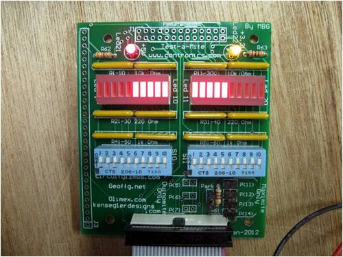
|
||||
CircuitGizmos Guru Joined: 08/09/2011 Location: United StatesPosts: 1425 |
Pure guessing on my part: > on Digital, switches 6 to 14 have no effect. Resistor pack not right? > On Analog switches 1 to 5 work OK but switch 6 only works if 7 is on also? Solder splash? Micromites and Maximites! - Beginning Maximite |
||||
bigmik Guru Joined: 20/06/2011 Location: AustraliaPosts: 2914 |
Hi Ronee, My guess would be that two of the resistor packs are backwards.. Can you tell me what reading you get in Analog tests with switch 7-10 OFF and in both positions of Switch 6? That should give me an idea of what is wrong with the resistor divider. See this image.. it shows two 6 pin packs for each (12 pin) resistor array. 
As can be seen the black dots (indicating Pin 1 - common-) should be at either end of the 12 pin Resistor pads.. If not that then I think maybe the resitor packs are `B' Type.. but I assume you bought them in the same batch and if half the leds are fine they must be the correct type. Looking at my circuit I expect the packs for R45-R49 and R50-R54 are in backwards. I have tested the unit with a Duinomite Mini and Maxi, a Maximite SM1 and a CGMMSTICK1. and all worked as expected.. If the LEDs do their LED chase ok then it must be the resistors associated with the switches, The switch should read as a LOW --- Aha maybe you have the incorrect value for R45-R49 and R50-R54 -- Should be 1k Ohm, Or you have used the incorrect value for R5-R9 and R10-R14 --- Should be 10k (if you installed a lower value then the switch would be pulled too much to +3.3V and cannot be pulled low so will always read as a High. Let me know how you go. regards, Mick PS. I have just realised that the Maximite can have 10 Analog pins and I am only testing 6 so there will be a new version of the Tester program in a few days. regards, Mick Mick's uMite Stuff can be found >>> HERE (Kindly hosted by Dontronics) <<< |
||||
| ronee Newbie Joined: 08/01/2012 Location: CanadaPosts: 20 |
The board is nicely resist coated so hard to get solder slashes The white blobs on the board are just flux splashes and the way they have photographed. But thanks for the come back. Ron 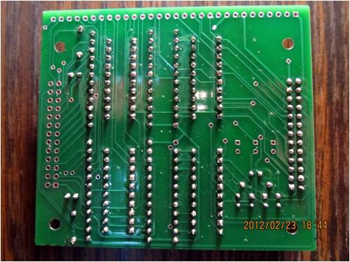
|
||||
bigmik Guru Joined: 20/06/2011 Location: AustraliaPosts: 2914 |
Hi Again Ronee, unplug the TAM from any `mite and power sources and try the following using a multimeter. Please switch all switches to the OFF position and then switch sw-6 ON.. You should be able to measure 10k OHM between pin(6)and +3.3v and 1k OHM between Pin(6) and GND See attached image for the relevant pins looking into the 26pin MALE header Let me know what you see. Regards, Mick 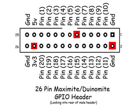
Mick's uMite Stuff can be found >>> HERE (Kindly hosted by Dontronics) <<< |
||||
| ronee Newbie Joined: 08/01/2012 Location: CanadaPosts: 20 |
Hi Ronee, My guess would be that two of the resistor packs are backwards.. Can you tell me what reading you get in Analog tests with switch 7-10 OFF and in both positions of Switch 6? That should give me an idea of what is wrong with the resistor divider. See this image.. it shows two 6 pin packs for each (12 pin) resistor array. 
As can be seen the black dots (indicating Pin 1 - common-) should be at either end of the 12 pin Resistor pads.. If not that then I think maybe the resitor packs are `B' Type.. but I assume you bought them in the same batch and if half the leds are fine they must be the correct type. Looking at my circuit I expect the packs for R45-R49 and R50-R54 are in backwards. I have tested the unit with a Duinomite Mini and Maxi, a Maximite SM1 and a CGMMSTICK1. and all worked as expected.. If the LEDs do their LED chase ok then it must be the resistors associated with the switches, The switch should read as a LOW --- Aha maybe you have the incorrect value for R45-R49 and R50-R54 -- Should be 1k Ohm, Or you have used the incorrect value for R5-R9 and R10-R14 --- Should be 10k (if you installed a lower value then the switch would be pulled too much to +3.3V and cannot be pulled low so will always read as a High. Let me know how you go. regards, Mick PS. I have just realised that the Maximite can have 10 Analog pins and I am only testing 6 so there will be a new version of the Tester program in a few days. regards, Mick Mick, OK, I have used Bourns 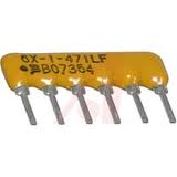
And I see they have writing starting from pin one. This then is the way they are installed with the "oB" in the square box, This means they alternate, printing, blank, printing, blank. R1 to R20 are 103lf (10 K) R21 to R40 are 221lf (220) R41 to R60 are 102lf (1K) The Analog test reads, 0.29, 0.29, 0.29, 0.29,0.29, 1.64 With switch six on or off. Turning on 7 gives 0.55 for six Ron |
||||
| ronee Newbie Joined: 08/01/2012 Location: CanadaPosts: 20 |
Hi Again Ronee, Please switch all switches to the OFF position and then switch sw-6 ON.. You should be able to measure 10k OHM between pin(6)and +3.3v and 1k OHM between Pin(6) and GND See attached image for the relevant pins looking into the 26pin MALE header Let me know what you see. Regards, Mick ] Mick, I see 10K between 3.3 and pin6 but nothing between pin 6 and ground Getting there Ron |
||||
| ronee Newbie Joined: 08/01/2012 Location: CanadaPosts: 20 |
Mick, I see 10K between 3.3 and pin6 but nothing between pin 6 and ground Getting there Ron Oops, I have the two inboard pins of the two resistor sets unsoldered! Face red...LOL Thanks for all the trouble shooting, I appreciate that Take care, Ron |
||||
bigmik Guru Joined: 20/06/2011 Location: AustraliaPosts: 2914 |
No worries Ronee, I gather it is working OK now? I am glad that someone has actually built one up, it is good to get feedback, if I can help further let me know.. I hope to get time tonight to add the code for Analog test to Pins(7-10) for MM .. Regards, Mick Mick's uMite Stuff can be found >>> HERE (Kindly hosted by Dontronics) <<< |
||||
| ronee Newbie Joined: 08/01/2012 Location: CanadaPosts: 20 |
No worries Ronee, I gather it is working OK now? I am glad that someone has actually built one up, it is good to get feedback, if I can help further let me know.. I hope to get time tonight to add the code for Analog test to Pins(7-10) for MM .. Regards, Mick Thanks Mick, Yes it works perfectly. Once you gave me what the resistances should be I was able find out where I had gone wrong. The old eyes aren't that sharp anymore and even with much magnification the missing solder was hard to spot. It is even viable in the bottom of the board picture I posted. Yep, recommend the Tester to anyone who wonders what their Maximite is doing. Cheers, Ron |
||||
bigmik Guru Joined: 20/06/2011 Location: AustraliaPosts: 2914 |
Great News, I know what you mean about your eyes, I used to amaze Don with my magical ability to spot solder shorts, splashes and missed solder from a metre away but now I almost need the hubble space telescope to see things... Anyway TESTER3.BAS is now available from Here Test-A-Mite It tests all 10 MM Analog Inputs now... Regards, Mick Mick's uMite Stuff can be found >>> HERE (Kindly hosted by Dontronics) <<< |
||||
| donrecardo Newbie Joined: 04/05/2012 Location: United KingdomPosts: 16 |
I hope to be building one soon too . I have ordered my pcb from Dontronics and sent for the parts I didnt have laying around from Farnell. I am just waiting for the post man to deliver them now so will let you know how I get on Dopn |
||||
bigmik Guru Joined: 20/06/2011 Location: AustraliaPosts: 2914 |
Hi Don, Great, Let me know how you go... Also dont put 10 way switches that are side activated (As I did in my photo) whilst they are high quality switches it is hard to select them in the area where the links are for Freq/count/period tests... Switches like Ronee used are good. Mick Mick's uMite Stuff can be found >>> HERE (Kindly hosted by Dontronics) <<< |
||||