
|

|
Forum Index : Microcontroller and PC projects : Wii Numchuck
| Author | Message | ||||
jman Guru Joined: 12/06/2011 Location: New ZealandPosts: 711 |
Hi All I have seen a few interfaces based on the Wii numchuck so i decided the Maximite needs one too. The Numchuck uses' an I2C interface The I2C address is &h52 and used in the "New Way" so the data in unencrypted The Initialize sequence is 2 bytes &hF0 and &h55 this only needs to be done once. Then set the read location to &h0 and read the required 6 bytes This litle gem provides a X-Y Joystick a 3 Axis Accelerometer and 2 butons not bad for $3.50 shipped Info on the Numchuck was sourced from here Wiki on Wiimote The Numchuck was souced from here Ebay Numchuck And the code is here 2011-11-20_091652_Maximite_NumChuck.zip Regards Jman |
||||
crackerjack Senior Member Joined: 11/07/2011 Location: AustraliaPosts: 164 |
Hi jman, Nice find and a good post. I've ordered a few of those little suckers - 3-axis accelerometer + 2 buttons + analog joystick for less than the price of a cup of coffee - delivered! I have some ideas to put them to some good use, but will obviously want to experiment first... Just a quick technical question while I await delivery... did you have to use pull-ups, or are they already in place on the device? Also, is 5.0V ok? Any idea on current drawn by them? Thanks again for the good info. Cheers, crackerjack. |
||||
jman Guru Joined: 12/06/2011 Location: New ZealandPosts: 711 |
Hi crackerjack I am using the 3.3V from the Maximite 3.3v rail Current consumption is 7.5ma so no troubles there. My Maximite has an RTC with pull-ups to +5V so i just left those in place. Hope this helps Jman |
||||
jman Guru Joined: 12/06/2011 Location: New ZealandPosts: 711 |
Hi Oone small gotcha the clone numchuck was odd colored wires they are White - SDA Blue - SCL Red - Ground Yellow and Green - +3.3v Thought i would make it a little easier for those you are going to try one Regards Jman |
||||
marcwolf Senior Member Joined: 08/06/2009 Location: AustraliaPosts: 119 |
Great project The little IR camera in the remote is also a very interesting little device. Shoudl work great with the Maximite Coding Coding Coding.. Keep those keyboards coding.. RAW CODE!!!!! |
||||
crackerjack Senior Member Joined: 11/07/2011 Location: AustraliaPosts: 164 |
Reviving an old post... I obtained a bunch of these extra cheap items from ebay and they are great. Really handy as hand-held controllers for almost anything and all via the I2C bus on the Maxi/Duino. To get the full 10-bit resolution data from the accelerometer's 3 axes, here are a couple of changes that can be made to jman's original code: [code] ... Accel_X = (RDBuff(2) * 4) + Fix(RDBuff(5)/2^6) ... Accel_Y = (RDBuff(3) * 4) + Fix((RDBuff(5) And &b00110000)/2^4) ... Accel_Z = (RDBuff(4) * 4) + Fix((RDBuff(5) And &b00001100)/2^2) ... [/code] Also, it's really easy to make a "breakout board"/adapter for the Nunchuck connector using a bit of old stripboard or better still some double-sided edge connecter from an old PCI card, etc. Have fun... |
||||
| yobortsa Newbie Joined: 12/12/2011 Location: AustraliaPosts: 37 |
I just received some clone nunchuck controllers from eBay and they have different colour coding to what jman listed above. Mine are: White - SDA Yellow - SCL Black and Brown - Ground Pink - +3.3v The pinout is shown on the board if you open the controller: VCC Pink DET Blue SCL Yellow SDA White GND Brown/Black I believe the blue wire is used for device detection on the WII and is tied to VCC, hence doesn't seem to be required on the Maximite. Here is the Maximite 3.0A code I'm using: Rem ReadWii Numchuck Cls GoSub Screen 50 Dim RDbuff(6) 60 i2caddr = &h52 ' Numchuck address 70 I2CEN 400, 100 ' Enable I2C 80 I2CSEND i2caddr, 0, 2, &hF0, &h55 90 I2CSEND i2caddr, 0, 2, &hFB, &h0 DisplayLoop: I2CSEND i2caddr, 0, 1, &h0 I2CRCV i2caddr, 0, 6, RDBuff(0) Joy_X = RDBuff(0) Joy_Y = RDBuff(1) Accel_X = (RDBuff(2)*4) Acc_X=Accel_X+Fix((RDBuff(5) And &b00001100)/2^2) Accel_Y = (RDBuff(3)*4) Acc_Y=Accel_Y+Fix((RDBuff(5) And &b00110000)/2^4) Accel_Z = (RDBuff(4)*4) Acc_Z=Accel_Z+Fix((RDBuff(5) And &b11000000)/2^6) If (RDbuff(5) And &h01) <> 0 Then Button_Z = 1 Else Button_Z = 0 EndIf If (RDbuff(5) And &h02) <> 0 Then Button_C = 1 Else Button_C = 0 EndIf Locate 111, 10 : Print Format$(Joy_X, "%3.0f") Locate 160, 10 : Print Format$(Joy_Y, "%3.0f") Locate 111, 50 Print Format$(Acc_X, "%5.0f") Locate 160, 50 Print Format$(Acc_Y, "%5.0f") Locate 210, 50 Print Format$(Acc_Z, "%5.0f") Locate 120, 90 Print Button_Z; Locate 169, 90 Print Button_C; GoTo DisplayLoop Screen: ' Setup Screen Locate 0, 0 Print "Joystick Position X Y"; Locate 0, 40 Print " Postion Sensor X Y Z"; Locate 0, 80 Print " Buttons Z C"; Return I question if crackerjack had the right bits for the extra two-bit resolution on the X and Z axis - his code doesn't seem to match the website: http://pinouts.ru/Game/nintendo_nunchuk_pinout.shtml I think I've written the code according to this website, but it's probably not really worth using the extra two bits anyway - too hard to move the controller in fine increments. It's a great little device for the menu on my car computer... David |
||||
crackerjack Senior Member Joined: 11/07/2011 Location: AustraliaPosts: 164 |
David. Thanks for pointing out the error in the code snippets I posted. They are incorrect and your updated code is correct. Cheers. |
||||
| BobD Guru Joined: 07/12/2011 Location: AustraliaPosts: 935 |
I received a couple of Nunchuks today. They have a plug on them like nothing I have ever seen before. What have you guys done to get them talking? Do you take the plug off? Bob |
||||
jman Guru Joined: 12/06/2011 Location: New ZealandPosts: 711 |
Hi Bob I just cut the plug off mine but if you dont like that idea take a look here http://olimex.wordpress.com/2012/02/07/duinomite-new-boards- t-shaped-breadboard-adapter-wii-nunchuk-to-uext-and-icsp-ada pters/ John |
||||
| BobD Guru Joined: 07/12/2011 Location: AustraliaPosts: 935 |
Thanks John I have an MM so it looks like I will be cutting the plug off. Post was 10 days from HK. Not too bad. Bob |
||||
crackerjack Senior Member Joined: 11/07/2011 Location: AustraliaPosts: 164 |
Aaargh! Don't cut it just yet! I made a small adapter from a stripboard edge, but a PCI card edge would work better. When a get a moment this evening from home, I'll post some pictures and details of the "adapter" I made. Cheers.... and put those cutters down! |
||||
| BobD Guru Joined: 07/12/2011 Location: AustraliaPosts: 935 |
CJ The cutters are down. No rush I won't do anything tonight (or tommorrow). Bob |
||||
crackerjack Senior Member Joined: 11/07/2011 Location: AustraliaPosts: 164 |
The home-brew adapter is a bit rough, but works pretty well. You will need a bit of stripboard of the sort that has vertical and horizontal copper strips (although the orginal Veroboard type might work with some ingenuity). You wil also need some single strand insulated wire, and 5 header pins. See below for stripboard I used: 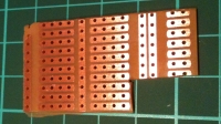
Cut the board so that you have three strips (vertical) at the edge and a couple of horizontal strips. A little bit of sanding and trial (avoid error) and you can get a little board that fits snugly into the Wii socket. The width is about 6mm, but it's best to start a bit wider and sand slightly until the fit is just right. See below: 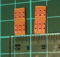
Next, solder a couple of "whiskers" onto the board. A (blurry) picture tells a lot of words; the main thing to note is that you should leave the insulation intact on the wites and solder one into each of the "horizontal" strips at the edges of the board. Leave enough wire to work with for later. See below: 
The next bit involves soldering header pins onto the board. The three pins going into the "vertical" strips at the edge of the board need to be soldered over the wire "whiskers" from the previous step. The pins will only just protrude through the board so thay can be soldered. Two pins are also soldered into the "horizontal" strips in the centre holes. More fuzzy, small images follow: 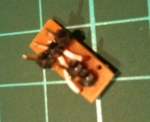
Almost done. The last bit is a little tricky... The protruding whiskers need to be squeezed into the tiny holes above the slot on the Wii socket. As the board is pushed into the slot, small springy metal tabs move up into these holes and so hold the wires in place. The trick is to get the wires in first before the board wedges the springy metal bits up too hard to get the wires into the gap. It may help to cut the wires to the right length (about the end of the board) and then very carefully, with *sharp* wire cutters, give the wires a chisel edge by cutting them diagonally at the end. It is important that the wires go into the two holes on the Wii socket where the middle connector is Unused, i.e. SCL & GND (image below borrowed from the WiiBrew wiki) and the edge connector part of the board connects to the VCC and SDA lines. The middle of these connections is of no importance to us: 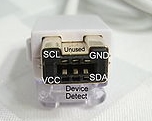
Finally, according to the connection labelled above, connect to your Maximite using some standard female connector leads. Voila: 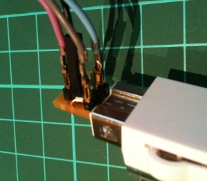
After all that hard work, grab a cold beer (mind you don't spill it on your benchtop), fire up the Maxi and have so much fun with your Wii Nunchuck that your wrist hurts. I'll be posting a full Wii Nunchuck Demo program in a day or so. Cheers - crackerjack. |
||||
| ArtBecker Regular Member Joined: 25/08/2011 Location: PhilippinesPosts: 47 |
There are several inexpensive commercial adapters available. Just do a Google search on Wii Nunchuck (or Nunchuk) Adapter. Remember, this is an I2C device, so the best adapters make provisions to add additional I2C devices. |
||||
| ksdesigns Senior Member Joined: 25/06/2011 Location: United StatesPosts: 143 |
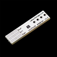
http://www.sparkfun.com/products/9281 ken |
||||
| Olimex Senior Member Joined: 02/10/2011 Location: BulgariaPosts: 226 |
Ken, our first design was like this and it easily slip off the joystick so we made this MK2 design: 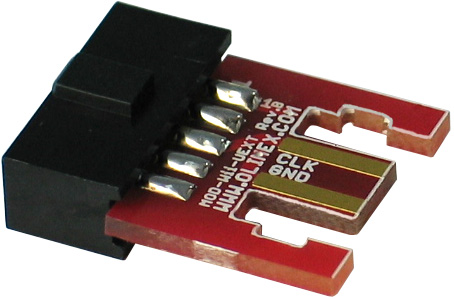
|
||||
| ksdesigns Senior Member Joined: 25/06/2011 Location: United StatesPosts: 143 |
very nice much better the others keep coming out .. ken |
||||
| BobD Guru Joined: 07/12/2011 Location: AustraliaPosts: 935 |
It looks good. Do you sell it? I looked at olimex and dontronics and could not find it. Link? |
||||