
|

|
Forum Index : Microcontroller and PC projects : Wood Fired Boiler Schematic
| Author | Message | ||||
pcaffalldavis Senior Member Joined: 17/10/2011 Location: United StatesPosts: 187 |
I've just about got the wood fired boiler schematic completed. It should be done today or tomorrow. I've been building it with the components on the bench and testing them using small BASIC test programs as it goes together. I have a question for someone with TinyCAD experience. Is there a command that will cause the wiring lines to remain straight when length adjustments are being made. Like when you need to extend a wire line? I seem to be spending a lot of time zooming in until the schematic is huge and then adjusting the lines so they remain straight. Some drawing programs give you the option of holding down a certain key while you drag a line to keep it perfectly straight rather than allowing it to go diagonally. Is there such a key combonation for this in TinyCAD? Pete in Hyder Alaska We're all here 'cause we're not all there. |
||||
TassyJim Guru Joined: 07/08/2011 Location: AustraliaPosts: 6097 |
Pete, When you select 'Wire' using F2 or the button, A wire tool popup should appear with free, 45 or 90 degrees as the choices. 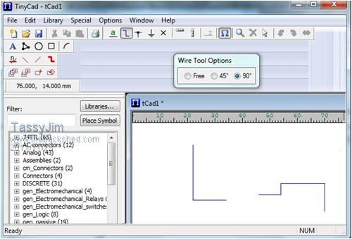
I did have a play with TinyCad a few years ago and it one of those thing I will get back to 'soon' (soon as the BOSS stops giving me more thing to do around the house). Jim VK7JH MMedit  MMBasic Help |
||||
pcaffalldavis Senior Member Joined: 17/10/2011 Location: United StatesPosts: 187 |
Thanks TassyJim. I've learned that it is best to get the line right the first time as adjusting it does not have the 90 degrees locked in. I can do any two segment lines fine, as TinyCAD handles this automatically. I just have not yet figured out how to draw a three or four segment line, and so I often have to go back and try to lengthen one of the lines where I didn't join the segments up exactly right the first time. Adjusting ends is where the entire line or one end of one goes off the 90 degree grid. I've about learned to do it two segments at at time though. My first schematic, the wood fired boiler is done. I going to put on some dots at the motors, fans and flow control valves that show which MM Pin controls them. You can always trace the lines back to the ribbon cConnector, but it might be nice to have this information at the object being controlled too. And this will help me make up the circuit board. We're all here 'cause we're not all there. |
||||
pcaffalldavis Senior Member Joined: 17/10/2011 Location: United StatesPosts: 187 |
Here is the schematic. I suppose it should come with a bit of explanation. The concept is a large wood fired boiler about 30’ from the house. It will be mounted on a slab of concrete and connected to the house through an underground 12” plastic drainage pipe. All the closed system recirculating boiler water will be pumped to the house and back through this pipe as will all the 24 VDC and 110 VAC electrical needs in the house. All power originates at the boiler from either an inverter or the 12 Volt CAT battery that drives the inverter. I suppose there will be one circuit of standard land line power. It will be from the house to power the 110 VAC to 12 VDC battery charger/ conditioner. This will keep the battery full up and conditioned in case the solar panel doesn’t get enough sun. This system should keep the system running through even the longest power outage with no interruption to heat. One of the primary benefits to wood heat is not worrying about power outages. I don’t intend to build a boiler system that gives up that advantage. 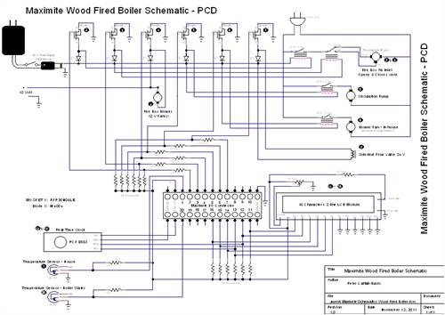
The boiler will be 4’ front to back, 6’ high and 3’ wide. The outer steel jacket contains the boiler water and the inner stove. The inner fire combustion box is about 4’ deep, 4’ high and about 2 ½’ wide. It is accessed through a large door in the front. There is a flue that ports from the front ceiling of the firebox just above the door and goes up and out the back. This exhaust gas tube is 8” diameter ¼” steel and will be within the water jacket below the upper water lever. The exhaust connects outside the back of the boiler to a 25’ tall chimney pipe, also 8” diameter ¼” steel. The entire boiler will be super insulated on the outside of the water jacket with Styrofoam and fiberglass. Over this an angle iron and 1” square steel tubing structure will be built and skinned with exterior painted metal roofing. An insulated removable top will be built also of metal and insulated with Styrofoam. The boiler with insulation and metal siding will be placed on the concrete pad and housed under a wood framed shed of only side walls and roof trusses. The shed will be open on both ends. The shed will be roofed with steel roofing. The roof extending all the way to the back corner of the house so it can be easily accessed during heavy winter snows. Snow depth on the ground here usually builds up to between 6 and 8 feet deep on the flats, much deeper on the building sides where roofs shed their snow. We have 10’ wide decks all around the house on the second floor. These are under the house roof line. On the main floor under the decks we have parking on each side in the front with with 10 to 15 cords of firewood at the back. This wood will be easily accessible to fuel the boiler all winter long. We use a rolling log cart that hauls about 1/6th a cord at a time. The wood fired boiler needs to be well insulated because it is housed outside, albeit under a roof and protected from snow backfilling on each side because of the shed’s side walls. There is an access door on the right side of the boiler’s exterior metal sheeting. Behind this panel are the connections for the electronics, pumps and drain valves. An LCD 16 x 2 line display or perhaps a 16 x 4 line will be installed on the outside of the metal siding next to the stove door. It will display the temperature in the house, the boiler water temperature, whether the circulating pump is running or off, and if the flow control valve is open or closed to the main radiator. Other information can be added if desired. Of course since the system comes with a built in Data logger I can set it up to log each opening and closing of the firebox air intake and each cycle’s duration. This will be helpful in determining efficiency and how long in burn time a full load of wood will last. This should also take into account the ambient outdoor temperature and desired house temperature, but with the addition of an external temperature sensor (outdoor) this could easily be done. I have not yet completed the BASIC program that will run the boiler but many of the sub routines have already been tested. I have not yet put them together as the boiler won’t be built until next summer (June, July & August). The program logic goes something like this: If the temperature in the house is below that desired, and if the boiler water temperature is less than 170 degrees F., then open the air intake at the front of the firebox below the door and for the first five minutes turn on the 12 volt 80mm fans which serve as blowers (old recycled computer power supply fans). These should bring the smoldering fire up to temperature quickly. Then, as the water temperature is still not up to 180 degrees F, the fire will continue to burn without the benefit of fans until the water in the boiler is 180 degrees. When the water temperature is over 150, and the house is colder than desired, the water circulation pump will operate continuously, probably all winter long. In addition to heating the house, the boiler water also circulates across a heat exchanger at the electric hot water heater. This will help heat the hot water supply in the house saving on electricity. Our household hot water already circulates in a continuous thermal wicking loop. This loop returns the hot water back to the bottom of the hot water heater. This is so we can have hot water almost instantly at any faucet, even on the upper level of the house. There will be either a hot water merge control to mix it with cold if the hot water temperature gets over 130 degrees F, or perhaps there should be a flow control solenoid at the water heater to prevent over heating the household hot water. Without such a control the household hot water would get too hot for use in the home. This is usually done with a temperature merge control, but in our hose with a thermal wicking loop such a merge valve won't work. If it turns out that this situation often happens in conjuction with an over warm house, then perhaps the best answer in these cases would be to just turn off the boiler water flow to the entire house by turning off the circulating pump. The schematic only shows two Temperature Sensors, one in the boiler water and one in the house, but another might be a good idea at the household water heater. Others might be added if additional heating zones are desired. Our house will very likely only need a single radiator. An outdoor Temperature sensor could be useful too in the spring and fall as the need for the entire system waxes and wanes as the weather gets warmer and cooler. Additional heating zones. All it would take to add an additional heating zone from the electronic point of view is another temperature sensor, a pin for another fan relay, and a pin for a flow control valve to the extra radiator in that zone. This means each additional zone requires only three I/O pins. Of course it would require an extra radiator and running additional tubing too. The fan in the house that could blow air across the radiator only comes on if the temperature is well below the desired temperature, or if your house does not circulate warmth naturally. Ours does, so I don’t expect the fan to get much use. I will be using a fan dimmer type of 110 V control switch at the house on the fan line, so we will have full fan control indoors if and when the fan is kicked on by the program. That’s about it folks. I’m planning at this time to fine tune the program next winter as the boiler begins to get some use. I have no plans at this time to provide any indoor temperature adjustments in the house, like most houses have thermostats. I want to set the program all from the SD Chip. If it needs adjustment I can always update the program on another computer and load it with a chip swap. I’m thinking there will be a couple different programs that I can run. One could be normal, winter. Others could be to just maintain the house above freezing if we should go away. This size firebox should hold enough wood for four days if fully loaded and if the system is given a very light heating load. I’m sure it will evolve until there will be a day/night program to keep the house cooler in the sleeping hours, but this will require an override input or interrupt somewhere in the house, like a button to press to return the program back to day mode. This of course would require the use of an additional I/O pin. For now I’m just going to try it with a single program for 24/7. I’ll worry about further efficiency for day/night adjustments after I get the system working. I plan on having a calibration program to calibrate the motor that opens and closes the intake air vent at the firebox for combustion. That will be a simple program that can be loaded (plug in a keyboard), and will turn the CCW and CW reversible motor that opens and closes the air intake until it is calibrated just right. Once in place the main program can be reloaded and restarted with no further adjustments required. Did I mention that the entire system runs off a large 12 Volt CAT battery hooked up to an inverter, 90 watt solar panel with controller and a quality 110 VAC to 12 VDC battery charger and conditioner? This is so the entire system will keep running during a power outage. We get them at least monthly in these parts. This will make life around these parts much easier. Since the only drains on the inverter are a circulation pump, a flow control valve (almost never activated), a house fan, (also almost never activated), and a small motor to open and close the firebox air intake vent, there is very little drain on the 110 VAC / Inverter / Battery from these sources. I expect the entire system could run for days without power if it has a fully charged battery at the time the power goes out, and if the solar panel contributes at least something during the power outage. Before I can get started next spring I first have to bring in about 20 10 yard dump-truck loads of gravel to bring the ground level up, trench out for the 12” pipe connecting everything to the house (the 1” insulated PEX water piping & electrical lines), pour the concrete pad, then drive 400 miles with a trailer to get a few sheets of ¼” plate steel and chimney stock. After that I get to then fabricate the boiler. Oh, and put it in place, build its outer skin frame, insulate and put on the metal siding. Then build the outer walls and trusses, put on the roof tin and siding for the exterior shed and start testing. Should be a fun summer. My next step this winter is to build the circuit board and get all the wiring and parts off the breadboard. I plan on leaving space for more MOSFET’s or other circuits so all 20 I/O pins can be driven if plans expand or change. Right now I have six pins available, but if I add two more temperature sensors as I think I will, then I only have four left. These could get used for additional flow control solenoid valves or fan controls. I forgot to mention that this boiler will be built using the relatively new super efficient type of air “injection type” of wood firebox combustion system. These are better than the catalyst type stoves that were all the rage until a couple years ago. These newly designed stoves take all the combustion air and pipe it up, across and along the sides of the stove inside the firebox where it is channeled into multiple stainless steel pipes that cross the ceiling of the fire chamber. Each of these tubes is drilled with two rows of holes all across their bottoms. All the combustion air except for one small 5mm hole passes through these tubes. In my unit there will be four 2” tubes. As I mentioned earlier, the exhaust gas vent (out pipe) for this stove is at the front above the door. All combustion gasses naturally go to the top of the firebox, swirl around the incoming air pipes and burn as the gas works it way forward to the front, up and out. These systems start to burn very clean at around 300 degrees F. At that temperature and above, the smoke output at the top of the chimney is almost invisible. As some of you will know, the temperature at which full combustion takes place in a standard catalyst stove is MUCH higher, 450 to 500 degrees F. The problem with these old catalyst stoves is that they take so long to get to the higher temperatures, consume more fuel getting to the higher temperatures, and burn additional fuel maintaining the higher temperatures. And the catalysts quickly plug up with soot as the fire eventually dies down with under temperature smoke still flowing through it. This is because you went to sleep and once the stove temperature dropped below catalyst temperatures you were not there to set the stove to bypass the catalyst. This is a basic flaw with this type of system if you ask me. I had to clean soot out of the catalyst at least monthly when the honey comb became completely plugged. I have had one of these fantastic new stainless steel air “injector” wood stoves for three years now and swear by them. I wanted to see this super efficient, low temperature and clean wood burning technology put to work in a wood boiler, but I could not find any such system in the marketplace. I approached one of the largest manufacturers of the air injector type of stoves to try and convince them to build a boiler system like this but they did not show any interest. And so I will do it myself. One of the problems with wood fired boilers is they are known for burning very smoky and dirty, sometimes polluting an entire neighbor hood. Some places have outlawed wood fired boilers entirely for this very reason. I believe that this modern air “injector type” of combustion system, coupled with a computer controller, that also blows air into the fire box to bring it out of standby mode and up to temperature very quickly will have none of these problems. A Maximite is perfect for this project! This type of system I think holds quite a bit of promise. Anyone that doubts this should take a look up inside the firebox of any air “injector type” stove when it is running. The holes in the stainless steel, where the air comes into the firebox, look just like propane gas jets once the fire gets up to 300 degrees. It is like looking at a commercial gas oven jet. The holes burn blue and from this you can tell most of the smoke which would have been going up the chimney is being re-burned before it leaves the chamber. Wood burners remember: Smoke is unburned fuel! Don’t waste your fuel. I have had a roof camera for several years that is focused on our roof and chimney. A seven inch monitor is right next to our the wood stove so we can tell at a glance what the plume of smoke looks like coming out of our chimney. When we changed from a catalyst stove to this new stove technology two winters ago the reduction we saw in our smoke output was unbelievable. Now we have almost no visible smoke, and we seem to be burning 20 to 30% less fuel each winter. Too Much Information? Sorry. I think some may be interested so I gave as much as detail as possible now. If you have suggestions or questions please feel free to ask. I have the time now, not so much I’m guessing once spring gets here in April or May. Cheers, Pete in Hyder Alaska We're all here 'cause we're not all there. |
||||
pcaffalldavis Senior Member Joined: 17/10/2011 Location: United StatesPosts: 187 |
Folks, Sorry the schematic image is so poor. It is readable at my end in its 186 Kb size, but once it arrived in the newsgroup it is no longer readable. If anyone would like to see a clearer image drop me a post. I'm happy to email it. Or maybe we could somehow get the moderator to show it as it was sent? Pete in Hyder We're all here 'cause we're not all there. |
||||
| ajkw Senior Member Joined: 29/06/2011 Location: AustraliaPosts: 290 |
Pete, My wife just asked if the Maximite will open the door and put the wood in ??? 
Cheers, Anthony. |
||||
pcaffalldavis Senior Member Joined: 17/10/2011 Location: United StatesPosts: 187 |
Na, that is what the wife is for. I get the wood, cut it, split it and bring it home. Her job is to stack and stoke! Ha! When she feels like it. That's pretty often though; she doesn't like to be cold. Pete We're all here 'cause we're not all there. |
||||
| ajkw Senior Member Joined: 29/06/2011 Location: AustraliaPosts: 290 |
Very good, looks like you have it all sorted. Mine reckons she has to do it all here including ringing the man to deliver it. She does get some help from me with the carting from front to back, stacking it and I do throw the occasional piece in. Only a small firebox inside the house is required here. Many many years ago I did a lot of cutting, splitting and stacking but we live on the coast now. I think you have come up with one of the biggest projects for the Maximite. I hope it goes well. Cheers, Anthony. |
||||
pcaffalldavis Senior Member Joined: 17/10/2011 Location: United StatesPosts: 187 |
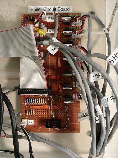
Got the design for the PCB done. All the low voltage connections 5, 12 & 24 with electronics fit easily on a 9 x 5.5 CM board. I managed to put 9 Mosfet switches and five connection points for temperature sensors. Still room left over. I will be putting 2 pin connections to PCD headers for all the relay and solenoid circuits as well as to each of the temperature sensors. Got a 26 pin shrouded header to connect it all to a MM SM1. There are also two 2 pin connections to headers for 12 V and 24 V power supply connections. I'm about done cutting the board and will start putting on components soon. I had to order in the 2 pin headers and connectors plus the 26 pin shrounded header so I can't do it all this week. Bummer. I have everything else. I don't plan to mount the MOSFETs to any heat sinks, but the only one that will be closed much of the time is the one that is sending 24 volts to the circulating pump relay. I'm no expert on electronics (as most of you can tell), but does anyone think that leaving these MOSFETs free standing with no heat sinks will be a problem? All are either driving 24 volt relay circuits or 12 volt computer fans to blow air into the firebox for 5 minutes each time the intake vent opens, no big load I don't think. Am I correct? Or should I think about finding a way to lay some of them down or attaching them to a heat sink? Thanks everyone. Pete in Hyder We're all here 'cause we're not all there. |
||||
| centrex Guru Joined: 13/11/2011 Location: AustraliaPosts: 320 |
Just wondering how Peters project is going, havent seen any posts for awhile. Would be most interested to see the pcb layout. regards Cliff |
||||
pcaffalldavis Senior Member Joined: 17/10/2011 Location: United StatesPosts: 187 |
I've been plugging away. We had four feet of snow this past 10 day stretch and have not been able to get mail (float planes can't see to get here through the storms). I have most of the add-on board done, but I accidentally ordered extra 10K resistors when I needed 10 Ohm resistors. So I can't quite finish it up yet. The add on board is about 1/3 the size of the SM1 so it is pretty cramped. I spent the day testing the four temperature sensors sections of the PCB. Those don't require any 10 Ohm resistors. That took all day 'cause I didn't see the tiny specks of wire or dross that had fallen between two lines shorting out two of the four temperature sensor connections points. Some days are like that. Tonight I'm going to test the LCD connection point using another 16x2 LCD that arrived. When that is done I can't really do anything until the 10 Ohm resistors arrive. Then I should be done with the PCB and will start on the line current panel with all the relays. I'll post photos of the small PCB when the resistors arrive. I used the type of prototype board that has rows of etched holes. I use a knife to cut the rows as needed so I have sufficient holes in a row to jumper each grouping of components. The back side has about 30 jumper cables, but the front looks pretty clean. I am using two pin headers and two pin connectors to connect all the relays, 12 & 24 volt exterior power supplies, and temperature sensors. I'm using a 26 pin connector on the board to connect it to the SM1 and I'm using a 10 pin connector to jump it out to the 16x2 LCD. That's about it. We might get mail on Monday and if we do I'll have the photos of it next week. Thanks for asking! I'll keep you posted. Pete in Hyder We're all here 'cause we're not all there. |
||||
pcaffalldavis Senior Member Joined: 17/10/2011 Location: United StatesPosts: 187 |
Here is a photo update of the Wood Fired Boiler Control Panel. I'm uploading nine. If they don't all get through I'll try sending them in additional posts. The TFT monitors are still not here, but I have a VGA to composite converter shown in one photo. It is running and sends the screen display into our CCTV security system. A photo of the display is included in the group. You can see a 10 pin connector on the Boiler Component PCB. I ended up not using it instead favoring the VGA to Composite converter. 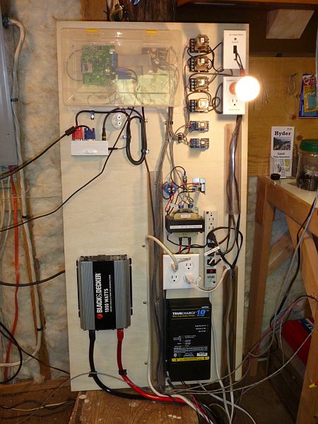
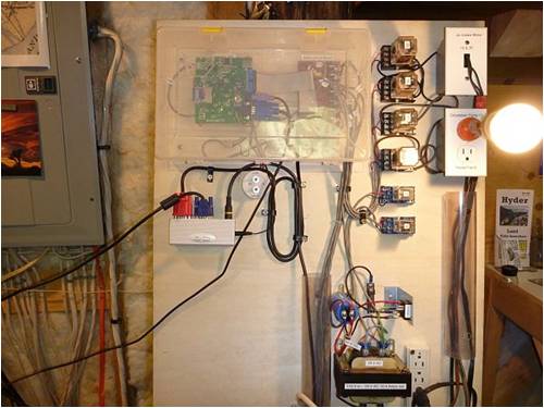
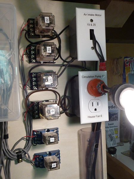
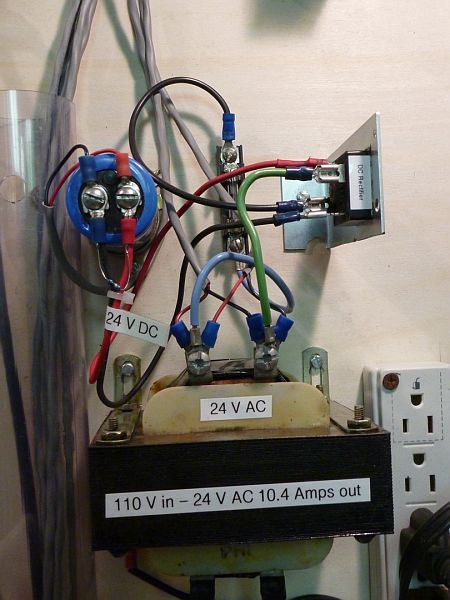
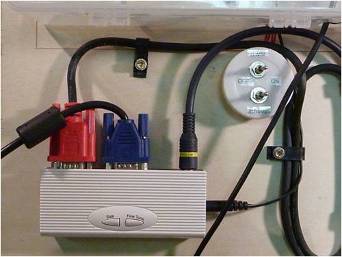
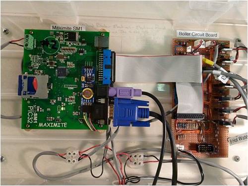
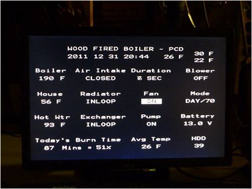
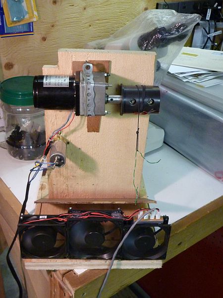
The last photo shows a shop mock up of the air intake for the fire box. It opens when the water temperature gets down to 170 F, the air intake opens, and the fans will blow for a set period of time to get the fire up to temp quickly. Then the fans stop and the intake remains open until the boiler temperature gets up to 190 F at which time the air intake closes. Hot air is drawn off in the house through the radiator and hot water heat exchanger as needed until the boiler water temperature drops back to 170 and the entire process starts over again. HDD in the display is the number of Heating Degree Days for today. This is a standard used to compare efficiency and heating costs of same or similar structures in different climates. Heating Degree Days are usually added for an entire heating season (in NA that is Sept 1st through Aug 30th). HDD’s are also a good way to determine at which outdoor temperature your home heating system is most efficient. Kind of like finding the most efficient driving speed to fuel consumption ratio. It will be nice to know at what average outdoor temperature our boiler is most efficient at keeping our house the desired temperature using the least amount of fire wood per HDD. If anyone has any questions please don't hesitate to drop a note or ask in the group. Thanks to everyone that helped get me this far! Pete in Hyder We're all here 'cause we're not all there. |
||||
| centrex Guru Joined: 13/11/2011 Location: AustraliaPosts: 320 |
Hi Pete That is very impressive, although I dont know if an electrician saw it he would be impressed. But it is your design and the beauty is if it doesnt work quite as expected you can get in and do something about, not so if it was a turnkey system. Keep up the good work, MM forever. Cliff Cliff |
||||
| centrex Guru Joined: 13/11/2011 Location: AustraliaPosts: 320 |
My little lcd screen has just been delivered, from China. What a beauty it should go very well with your SM1 and the boiler control. Just plugged it in and away it went. It only took a couple of weeks to get here and that is over the Xmas/new year break. Cliff Cliff |
||||