
|

|
Forum Index : Microcontroller and PC projects : Temp data logger w LCD & RTC!
| Author | Message | ||||
pcaffalldavis Senior Member Joined: 17/10/2011 Location: United StatesPosts: 187 |
Cheers everyone. I got my first Maximite Temperature logger completed and running. It is on a Dontronics Maximite SD1 with an added RTC and a 16x2 LCD. Works great. I finally found a use for those old plastic VHS tape boxes. The entire project fits inside. 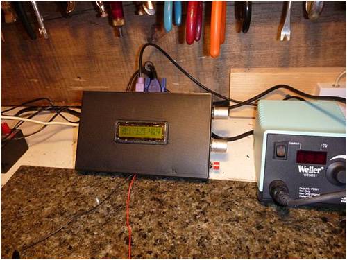
The LCD displays through the front cover. The two POTS, one to adjust the lightness/darkness of the LCD characters, and the other to fine tune and calibrate the sensor are mounted in one end of the case. So is the micro on/off switch for the LCD back light. I chose to have it display the date and time on the top line of the LCD and on the bottom line I have the current temp in the middle, the daily low on the left and daily high on the right. At midnight each night it writes the daily high, low and average to the SD chip. I use this information each year to calculate heating degree days, first freeze, last frost, the growing season length. And I track record annual high and low temperatures. This is all interesting if not useful information for our local community of about 100 people. I put it on our local annual calendars which we print and pass out each December. 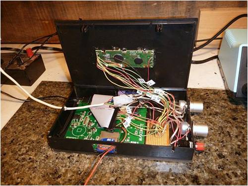
It is hard to see the RTC but it is under the cables hot melted into place on the Maximite SD1 board. In addition to being an almost fail-safe data logger, the unit makes a nice temperature display for my shop. Knowing today's high and low at a glance is also a nice feature. This data logger aspect to the SD chip is going to make my work logging the daily highs and lows MUCH EASIER. Right now I have it running off a 9v one amp power supply but I will be hooking it up to a 12v battery system charged by a PV panel and an on-grid battery charger and conditioner (for those times when the sun don't shine). We have power outages almost every month so this should solve the problems all the resets might cause including loss of part of each days data (highís and lowís collected before the power went out). Speaking of power outages we have had FOUR today! I do have a couple questions for those more knowledgable than myself. My Maximite SD1 reads 3.26 volts on the 3.3 volt leg. I adjusted the Basic program so 3.26 is used to calculate the temperature (Being Iím in the US I then convert everything to Fahrenheit). What Iíve noticed is that when I turn on the back light for the LCD the 3.3 volt leg drops from 3.26 to 3.06 volts. This of course throws off the temperature reading as the voltage has changed so much. I can recalibrate with the back light on or off, but then switching the back light off or on again will require another recalibration. Does anyone have any idea why this is and how to deal with it? My other question shows perhaps how much of a newbie I am. The adjusting POT for the temperature is 10K and is VERY sensitive. Most of the adjustments are right in the middle of the dial. If I wanted to decrease the sensitivity of the POT knob couldnít I put in a 1K POT with a 9K resistor in series on the middle leg? Would this give me a wider range of rotation on the knob for the fine tuning? Or since I'm in the middle of the dial should I maybe put in a 4.5K resistor with a 1 K POT? Right now using the 10K POT the smallest adjustment or touch to the knob is often too much. I want to thank everyone for all their help with the RTC, LCD and Temperature sensor programs. I love the Maximite, the SD1 and will be using it for many other projects. This is only a beginning. Yahoo! Pete in Hyder Alaska We're all here 'cause we're not all there. |
||||
| Ray B Senior Member Joined: 16/02/2007 Location: AustraliaPosts: 219 |
Nice to find a use for those VHS boxes. Re the LCD power supply dropping can you consider using a 5v supply? This may also deal with your contrast problems with a more stable supply voltage. My statements are based upon the original design MM which has 5 volts available, I don't have the schmatic for the SD1 at hand. Do you intend publishing the code & schematic? Cheers RayB from Perth WA |
||||
pcaffalldavis Senior Member Joined: 17/10/2011 Location: United StatesPosts: 187 |
Hello Ray! I suppose I could use a separate 5 volt power supply but I didn't want to if I didn't have to. The SD1 Maximite gets it 3.3 and 5 volt rails right off the Maximite. It is not a separate LCD power supply that is dropping exactly, but rather the act of turning on the LCD back light drops the voltage all across the Maximite. It is on the 5 volt rail, but both Maximite rails drop when the back light is turned on. Is this normal? How much current could the back light draw on a 16x2 LCD? The LCD contrast is not a problem. It works fine with a 10K POT. It is the adjustment to the LM335 temperature sensor via its 10K POT knob that is too sensative. I don't know enough about electronics to know how to expand the turning radius for calibration. Using simple math, which may be wrong, I figured if I was currently in the middle of a 10K POT and it was too sensative, that it might be better to have a 4.5K resistor in series on the middle leg of a 1K POT. To my logic (with little understand of the whole process) I can't help think that this will give me an adjustable resistance range from 4.5K to 5.5K using this set up. Am I right? Will this likely allow me a larger turning arch to achieve a finer adjustment? Right now with a 10K POT all I have to do is touch the knob and it will likely move at least 2 degrees up or down (F) which is too much for real accurate calibration. Never thought about drawing up the schematic. I don't have any software to make it look nice so probably not, but the good news is that I just wired in the LCD and RTC like folks on the forum have done. And the LM335 temperature sensor is on pin 1, the 5 Volt leg & Ground. Are there any free programs for drawing electrical schematics you could point me toward? 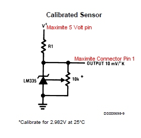
I am happy to share the code. I tend to renumber prgorams once I get a draft version working. This way I can finalize things by inserting up to nine lines between any two other lines. So my line numbers don't match up with the original programs found on the web sites or in the forums. Right now I use the autorun.bas on startup to get the date and time string from the RTC, then I have the end of the autorun.bas program launch my main program. For me that is templog.bas. If folks are interested in seeing templog Basic with the different line numbers I'm happy to share. Remember that I have converted the program from Celsius to Farenheit. If anyone wants to see templog.bas or my version of autorun.bas to get the date and time just let me know. I sure wish I could learn how to get a wider knob turn to calibrate the temperature sensor. Ah, every day a little bit more. I have read my way back to page 7 of 20 in this forum's list of topics. Very interesting. Next I'm going to learn to pulse an LED on Pin 5 & then Pin 18, just for fun! After that I will learn to trip relays based on temperature readings. All fun! Pete in Hyder We're all here 'cause we're not all there. |
||||
| Keith @ Senior Member Joined: 19/06/2011 Location: AustraliaPosts: 167 |
Pete I suggest you check to see if the pot is linear or logarithmic. Check this using a multimeter. Also measure the full on resistance value position on the pot and likewise the off value. Have look at this wiki article .... http://en.wikipedia.org/wiki/Potentiometer Hope this helps. Keith The more we know, the more we know we don't know ! |
||||
crackerjack Senior Member Joined: 11/07/2011 Location: AustraliaPosts: 164 |
Hi Pete, It would seem to me that the current drawn by the LCD backlight is causing your voltage to drop - you asked the question "How much current could the back light draw on a 16x2 LCD?"... If you have a multimeter, why not test it to see? You mention you are powering the setup from an external source - since the Maximite's 3.3V regulator takes it's input from the onboard 5V regulator in that case, have you checked the voltage at the 5V output with and without the backlight on. If the input voltage to the 3.3V regulator drops below 4.75V, anything can happen - see the datasheets for the LM1117T-3.3 for more info. Regarding the pot... are you using a multiturn preset? This could help.  |
||||
| Ray B Senior Member Joined: 16/02/2007 Location: AustraliaPosts: 219 |
As per previous posts: 1. Use a 10 turn linear pot & setting temp sensor will be a lot less sensitive to adjustment. 2. Measure the output voltage of 5V regulator - that should stay consistant at 5 volts else you have a large current draw somewhere - possibly from how you have the LCD wired especially on that bit of stripboard your using. Is the 5Volt reg too hot to touch? 3.The backlight seems to be the source of your volt drop is it wired correctly ? - once again look at the stripboard for a link between tracks. For a schematic drawing package try Eagle freebee from "www.cadsoft.de/freeware.htm" will do drawings & export to the PCB design module Found Hyder on Google Earth - is your store the "General Store" on Main St - nice little part of the world - have any problems with polar bears around your bins or are you a bit too south.? RayB from Perth WA |
||||
pcaffalldavis Senior Member Joined: 17/10/2011 Location: United StatesPosts: 187 |
I appreciate all your suggestions. After some further testing I learned I have a LCD with a backlight that has a voltage range of 3.5 to 4.5 volts. The 3.3 volt rail is not high enough to power it on mine (3.26 volts), and the 5 volt rail at 4.98 volts is too high. Perhaps the LCD back light dumps the extra voltage causing the large drain and voltage reduction across the entire Maximite. When I ran the LCD Back light on 4.5 volts from an exterior power supply it only consumes 115 mA, about the same as my Maximite which draw 130 mA. My cheapo multimeter only reads amperage up to 1000 mA and when I try to test the current load for the entire Maximite with the LCD back light turned on it is overloaded, so more than 1 amp. I was able to put a 10 K POT on the back light circuit and when it was dialed down to 25 Ohms the 3.3 volt leg on the Maximite only changed from 3.26 to 3.25 volts when the back light was turned on. I donít have any 25 Ohm resistors, the smallest in my inventory is 100 Ohms. When I put one of those in the backlight power line the backlight is so dim it is almost as dark as being turned off. Guess I need to pick up some 25 and maybe 50 Ohm resistors to round out my collection. Or maybe some small trimpots. Regarding the 10K Pot to calibrate the LM335 temperature sensor, it seems to be a regular POT. It is just a bit too sensitive for my liking. How might I go about decreasing the sensitivity? I want to have more turning radius per resistance change. Is my thinking about putting a 4.5K resistor in series with the middle leg of a 1K POT a workable solution? If I understand correctly wonít this give me a range of 4.5 to 5.5 K Ohms? And will this accomplish what I want? I like the multi turn POT idea. I was not familiar with those and will get some. That is probably the answer but is my thinking on the 4.5 resistor in line with a 1K POT workable? I'd check it myself but I only have 10K POTs right now. Regarding the request for my schematic, I wired the Real Time Clock SCL & SDA lines directly into via holes on the Maximite SD1 board. I used a PCF 8563 I got on Ebay for $5.50 USD. Wired the SCL to a via on the PCB that traces directly to connector Pin 13. Wired the SDA to a via on the PCB that traces directly to connector Pin 12. You can see these on the bottom of the SD1 PCB if you look closely. I also use Pins 12 & 13 to drive the LCD, but since the clock only uses these SDI pins at startup there do not seem to be any conflicts. The RTC can run on either 3.3 or 5 volts so connect it up to which ever you wish and ground is ground. I didnít get to wiring up the clock on my #2 Maximite SD1 last night but will do it tonight. If anyone wants a photo of where I wire these in just let me know and Iíll post a photo to this thread. We are a few hours off your time in this part of the world. You are about 18 hours ahead of me I think. Right now it is 4:50 PM Friday evening November 4th. It will be interesting to see what time this is shown as posting. Nope, the Hyder General Store is not mine. I live a few blocks away back in the woods. The coordinates for my house on Google Earth are: 55į54'58.36"N 130į 1'45.27"W Paste that into Google Earth, turn on Terrain, and tip her back to see the mountains. That's home! Elevation 6', better than 6' under! We're all here 'cause we're not all there. |
||||
crackerjack Senior Member Joined: 11/07/2011 Location: AustraliaPosts: 164 |
Pete, an Amp seems like a lot of juice for that setup to be sucking! I'd say some heat and smoke might be in the pipeline next. Don't go turn your temp. logger into your water boiler. Seriously though, four 100 ohm resistors in parallel make 25 ohms. And try your theory using the 4.5k (4.7k?) resistor with a 10k pot. You should get 4.5 to 14.5 k ohms, right? Experimenting is fun! Cheers. |
||||
TassyJim Guru Joined: 07/08/2011 Location: AustraliaPosts: 6097 |
Pete, I am using LM335's in my data logger and I didn't bother with the 10k adjustment pot. I found it easy enough to do the calibration in software. It's still only a single point calibration and one less part to worry about. Jim VK7JH MMedit   MMBasic Help |
||||
pcaffalldavis Senior Member Joined: 17/10/2011 Location: United StatesPosts: 187 |
I didn't know two like resistors in parallel resulted in half the resistance. I'll try that. In my other theory I was saying I would swap out the 10K POT for a 1K POT and add a 4.5 or 4.7 K resistor onto the middle leg. So I guess that would give me a range of 4.5 to 5.5K? And wouldn't this put the 1K spread across the full knob rotation? As it is currently I have 10K spread across the entire knob rotation. If my plan is correct it would make the knob rotation cover 10 times the degrees of rotation for the same change in Ohms. I realize it would limit the range of adjustment to 1K from only 4.5 to 5.5K. If this is correct I'll order up some 1K POTS. We're all here 'cause we're not all there. |
||||
| johnbig Newbie Joined: 23/06/2011 Location: AustraliaPosts: 21 |
Hi Pete, There is usually a 20,22 or 25 Ohm resistor in series with the backlight of those displays. This might limit your current to a reasonable amount. John Leate |
||||
| Keith @ Senior Member Joined: 19/06/2011 Location: AustraliaPosts: 167 |
Pete If you want a self adjusting brightness I suggest using an LDR (light dependent resistor) ... see this article for info ... http://www.doctronics.co.uk/ldr_sensors.htm#possible Now for the best part .... use PWM (pulse width modulation) to do the dimming and brightness control. The maximite can measure the resistance of the LDR on one of it's inputs and adjust the PWM on an output for the LCD brightness. I've tried to find the details in this forum where someone was dimming an LED using the Maximite and PWM but witout luck. Maybe some one can help. Keith The more we know, the more we know we don't know ! |
||||
| Ray B Senior Member Joined: 16/02/2007 Location: AustraliaPosts: 219 |
Pete, further to your request for free schematic editors follow this link which you may not know about for a stripboard design program http://veecad.com/editors.html Keep you busy as you start to get snowed in this Winter. RayB from Perth WA |
||||
pcaffalldavis Senior Member Joined: 17/10/2011 Location: United StatesPosts: 187 |
Wow Keith, PWM does sound cool. I have some Light dependant resistors. Got these to do the fridge test program. I got the back light on the LCD working now. I put three 100 Ohm resisters in parallel and it works great. There is no voltage change on the 3.3 (3.27) volt leg now whether the back light is on or off. PWM sounds cool but for this project a working back light should be good enough. And JohnBig, you must be right. That is exactly what I needed to make the back light on the LCD work. I will live with 34 ohms, but when I had a POT attached it read that it would work between 23 and 40 Ohms before the unit started drawing too much amperage, I guess from too much voltage and possible shunting the excess to ground? I donít know but it works now. And TassyJim, you are right too. Now that I have the back light working without causing any variance in the 3.3 volt leg I donít need the POT for the calibration so I took it out. Now for an update. I'm building two more MM SD1's with RTCs. Someone asked how the RTC was wired in. Tonight I had two to do and I put the first one in with the two SDI wires on vias in the PCB and the power lines to the cable connector upper row of pins. Unfortunately this brand new Maximite SD1 is dead. Well, not dead exactly. It will boot and load programs, but when I ask any program to run it hangs. I flashed a newer version 2.7A onto it but same problem. No workie. I donít know if my soldering the SDI wires to the via holes so close the PIC cooked it a bit too much or not, but does not work. Too badÖ Iíll need to get another one now. This is the same way I wired in the RTC on my first Temprature data logger shown in the beginning of this thread. 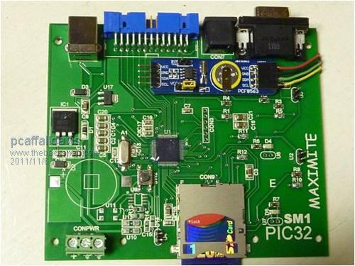
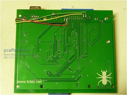
So, I put the same RTC on my third MM SD1 (photos above) and this time I soldered it to the bottom PCB ribbon pin connector points. It works great. I should perhaps note again that my first Temperature Data Logger with RTC and LCD 16x2 display had the RTC installed to the via holes and that one works just fine. Maybe I got a bad SD1 but it is too late to know if it was DOA or not as I didnít test the RTC first using jumpers. Iím going to make one or two more of these Temperature Data Loggers with 16x2 LCD displays. They are nice to have around in different rooms just as thermometers showing current temp along with todayís high and low. We have had 10 inches of snow overnight while I worked. Whew! And it is still snowing. Oh, Nope we donít get polar bears, but we have more Grizzlyís and blacks than nearly any other place in Alaska. One of the only two official US Forestry bear viewing areas in Alaska is 3 miles up the road from Hyder. I guess our winter has finally started. We had a couple inches of snow in October. So far this month we had a four inches one day, and now another 10. Typically we get between 20 and 40 feet here. That compresses down to about 8í deep on the ground in March in a heavy year and about 4 feet deep in a light year. Course where the snow sheds off the roofs it really stacks up. Iíve seen the piles of snow on the sides of our house higher than the second floor deck, and it is 13 feet above the ground. Thanks for all your help everyone! Pete in Hyder We're all here 'cause we're not all there. |
||||
TassyJim Guru Joined: 07/08/2011 Location: AustraliaPosts: 6097 |
And there I was upset when my air conditioning broke down last weekend! No bears here either but the snake season has started. 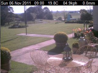
The weather data along the top of the image is from a Maximite of course. (The Maxi isn't up to putting the data on the image, just gathering it) Jim VK7JH MMedit   MMBasic Help |
||||
pcaffalldavis Senior Member Joined: 17/10/2011 Location: United StatesPosts: 187 |
Tassey Jim, No snakes anywhere in Alaska. One of the benefits I suppose. Nice photo. I should have taken a photo this morning before the grader plowed our driveway but alas and alak, I did not. What collectors do you use for your anamometer and rain gauge? And how do they tie into your MM? Nice photo! and HOT Pete in Hyder We're all here 'cause we're not all there. |
||||
| Ray B Senior Member Joined: 16/02/2007 Location: AustraliaPosts: 219 |
More of Jims' work can be seen here http://www.c-com.com.au/stowport.htm Waiting for Jim to publish his Liberty Basic code This LB forum link refers:http://libertybasic.conforums.com/index.cgi?board=com port&action=display&num=1319293865 RayB from Perth WA |
||||
TassyJim Guru Joined: 07/08/2011 Location: AustraliaPosts: 6097 |
Rain gauge etc from http://www.argentdata.com/ They use reed switches for wind speed and rain and resistors for direction. All my previous sensors have not lasted very long so I am going to build some heavy duty gear when time permits. On the MM, I use the counters for rain and wind speed as well as a couple of water flow meters. The analogue inputs do the temperatures, humidity and battery volts. Currently the MM is plugged into a laptop but I will be shortly changing it to a serial to Ethernet converter so the laptop can be shifted inside where it can do other duties. I have an application written in Liberty Basic on the laptop which does the logging and image manipulation. On another PC I run another application which does the pretty charts etc. Jim VK7JH MMedit   MMBasic Help |
||||
| Ray B Senior Member Joined: 16/02/2007 Location: AustraliaPosts: 219 |
Tipping Rain Gauge link follows: http://park18.wakwak.com/%7Eweather/archive/RainGauge.htm RayB from Perth WA |
||||
pcaffalldavis Senior Member Joined: 17/10/2011 Location: United StatesPosts: 187 |
Thanks for the TinyCAD link. I'm learning to use it. Can't really say this is anything more than a wiring diagram, but it shows how I wire in the PCF8563 RTCs to the MM Dontronic SM1's. I don't actually use the pin connectors, but rather solder the jumper wires to the ribbon connector junction points on the bottom of the board. This leaves Pins 12 & 13 free for other uses since this SDI channel only operates at startup. You can run the RTC on 3.3 or 5V sources; I just happened to put in on the 5V side. 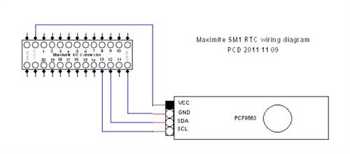
By the way, to those who might recall one of my new SM1's was non-responsive once a program RUN command was executed; Turns out it does run BASIC programs, it just does not display to screen from that point on. So it is more like a EV than an SM1, but the programs do execute just fine. Don was nice enough to give me a break when I ordered a replacement and another one. I guess most folks already know what a great and fair guy he is. But here is another thank you. THANKS DON! All for now. Gotta get back to my projects. I got a 110V reversable motor controlled through a 24 volt relay, controlled by the MM. It is on the breadboard but still good to see I can make it work. The little motor is geared way down to about 2 RMP and will be used to open and close the air intake to the wood fired boiler I'm building next year. When the temperature in the water jacket around the fire box gets above 180 degrees F, then close the air intake. When the temperature falls below 170 degrees F, then open the air intake. It is nice to see things take shape. I guess I'll pretty much end posting to this thread now. I never did the schematic for the 16 x 2 LCD, but that's been done elsewhere too. Chow! We're all here 'cause we're not all there. |
||||