|

|
Forum Index : Microcontroller and PC projects : Eagle Designed MM I/O Card
| Author | Message | ||||
| Ray B Senior Member Joined: 16/02/2007 Location: AustraliaPosts: 219 |
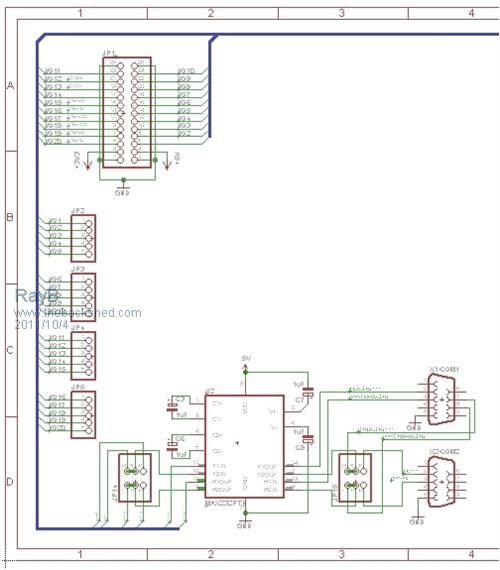
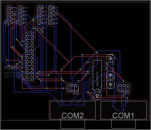
After more than 40 years of being involved with electronics I thought it was about time to actually design & make a PCB instead of purchasing pre built kits or using many metres of veroboard over that time. First question what design program to use ? Finally decided to give Eagle a run especially that this month Silicon Chip mag will be promoting Eagle. Attached is a board I've neally got available to release to others on this forum who would like the schematic / board files. This board was designed using these principles: * Had to be the basis of future MaxiMite I/O boards using the 26 pin connector. * Had to work within the board limits of the Eagle Lite software being 100 / 80 mm * Single sided for first attempt at making a PCB The attached draft design board that I've neally got finished features the following: * Has 26 pin I/O connector as well as 20 I/O connectors to link into a piece of protoboard. * Has both COM1 & COM2 of the single MAX232 chip but with links to disable COM2 and use the lines through MAX232 for RTS/CTS on COM1 Excuse the 26 pin connector not being on the edge of the board and all of the top layer links but that is what you get with a single sided board. 
Board has some space so I'll try to squeeze in some I/O isolation transistors ccts and a headed to connect to a LCD. Once I'm comfortable with the design I'll release the Eagle files for other to use / modify as they see fit for non commercial purposes. 
RayB from Perth WA |
||||
| vasi Guru Joined: 23/03/2007 Location: RomaniaPosts: 1697 |
Hi Ray, Good for you and success on your Eagle adventure. I think you are aware of this tutorial: http://www.sparkfun.com/tutorials/115 Vasi BTW, I may be wrong but what kind of COM connectors are you using? I think are not the good ones... at least this is how they looks to me (the pcb footprint and the traces routed around there). Hobbit name: Togo Toadfoot of Frogmorton Elvish name: Mablung Miriel Beyound Arduino Lang |
||||
| Geoffg Guru Joined: 06/06/2011 Location: AustraliaPosts: 3194 |
It looks like a double sided board to me; but don't restrict yourself to single sided - it is much easier to go double sided and it does not cost extra as all PCB fabricators start with double sided as a minimum. Also, watch out for the track widths, yours look rather narrow. Typically for a through hole design track widths would be 25 thou with a minimum clearance of 25 thou (but you can always go much smaller). A good design guide was written by David L Jones at http://www.alternatezone.com/electronics/pcbdesign.htm and he talks about track widths. It is well worth a read. Geoff Geoff Graham - http://geoffg.net |
||||
| Ray B Senior Member Joined: 16/02/2007 Location: AustraliaPosts: 219 |
Vasi - The RS232 Connectors would be Female DB9 connectors - I read the MM code that the MM is configured as a DCE (Data Computer Equipment) that send to a remote terminal (DTE). The board design in just based upon components off Eagle librarys and I'd not attempt a board until I had the hardware in hand to confirm. Vasi thanks for the tutorial link - I found some excellent Eagle tutorials on YouTube that I'd recommend to others as well as a forum on www.eaglecentral.ca Geoff - Yes it looks like a double sided board but that is how Eagle represents single layer with the wire links on the top side as shown in red and connecting through the green vias. The graphic above is just the output from the AutoRoute which I can see in not 100% but a good starting point which I'll need to hand adjust. I also see a T junction in the wire links which I'll need to fix as it has no via to terminate the wire link at. Other obvious issues are that is currently does not have the power pins brought out to connectors to link to a section of protoboard & maybe I should put is some decoupling / filtering caps on the power rails. Yes the track widths are a bit thin maybe to home etch but were just the Eagle defaults. After this exercise I can see the benifit of double sided boards but this is meant to be a trial using single sided board which I happen to have at hand. I'm also intending to use some lazer printed paper I got on ebay from Hong Kong. Regards RayB from Perth WA |
||||
| rhamer Senior Member Joined: 06/06/2011 Location: AustraliaPosts: 174 |
Ray, change the MAX232 to a MAX3232. The latter is a 3V part and will interface into the maximite directly. Cheers Rohan Rohan Hamer HAMFIELD Software & Hardware Solutions Makers of the Maximite Expander. http://www.hamfield.com.au |
||||
| Ray B Senior Member Joined: 16/02/2007 Location: AustraliaPosts: 219 |
Rohan note your recommendation to use MAX3232 which will work at either 3 or 5 volts but may be a bit harder to source e.g. altronics don't stock the 3232. Don't get me wrong but is there any other convincing reason to go for a 3232 or even use the 3.3 volt supply? My prototype on protoboard uses a MAX232 without even any pullups to the 5V rail (as discussed in MM manual V2.6 page 22) and seems to be working OK. I'm currently waiting for 10 x MAX232 from Hong Kong for total cost of $9.85 (inc post) so I'll see how they go. Regards RayB from Perth WA |
||||