
|

|
Forum Index : Microcontroller and PC projects : Board designers for our micro. projects
| Author | Message | ||||
| vasi Guru Joined: 23/03/2007 Location: RomaniaPosts: 1697 |
I don't talk here about classic PCB designers, I want to point at breadboard/perfboard/veroboard designers. The most interesting of them is Fritzing, with suport for almost all microcontroller boards form the market (Arduino/Basic stamp/Picaxe area). It supports three major boards, Breadboard, Perfboard and Veroboard(here you can cut traces to suit your schematic): 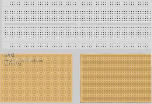
Arduino, MBed, Wiring, Basic stamp, and other boards: 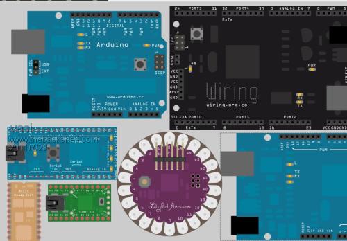
All Picaxe chips with their accessories and all Sparkfun board support (breadboards, sensors, etc.): 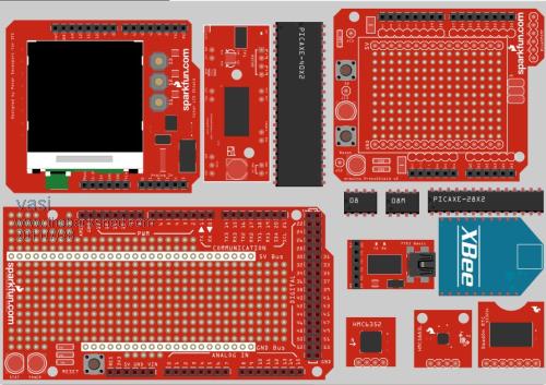
Perfboard area from those boards is interactive, you can place components... Also, all important components required to complete our projects. You can make your chircuit on any board you like, then you select the schematic window and arrange the components in a readable schematic (you can skip this if you want). Then, you select the PCB window, where you can design your final board and send the production files to any PCB fab house. Or you can DIY. The only bad thing is that it needs a decent computer to run at an acceptable speed. I have also another free Perfboard/Veroboard/PCB designer in mind but in another post... Hobbit name: Togo Toadfoot of Frogmorton Elvish name: Mablung Miriel Beyound Arduino Lang |
||||
| Gizmo Admin Group Joined: 05/06/2004 Location: AustraliaPosts: 5078 |
Nice find Vasi. Glenn The best time to plant a tree was twenty years ago, the second best time is right now. JAQ |
||||
| Ray B Senior Member Joined: 16/02/2007 Location: AustraliaPosts: 219 |
VASI Impressed with Fritz so far especially with the simple autorouter. What about your comment: " I have also another free Perfboard/Veroboard/PCB designer in "mind but in another post... " Regards RayB from Perth WA |
||||
| vasi Guru Joined: 23/03/2007 Location: RomaniaPosts: 1697 |
Thanks Glenn, When I first found this great program, I used it for illustrating my tutorials but hadn't so many components and features as today. The best way in getting familiar with it, is to start a little project. So, I started blinking two LEDs with a PICAXE 08M and this is how it looks on the breadboard: 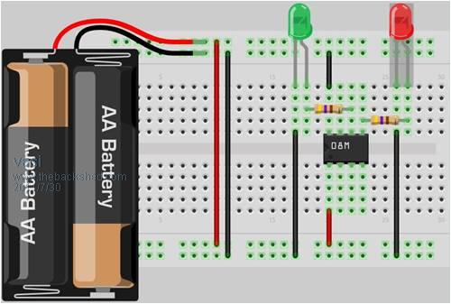
The battery from image have two cells but we need a source between 4.5V and 5V. Also, the required components for serial connection are not used here, we suppose we programed already our chip. On my breadboard, doesn't look as on project image but is electrically correct: At first, schematic look bad, you have the components randomly placed and you must drag/rotate them and to make connections: 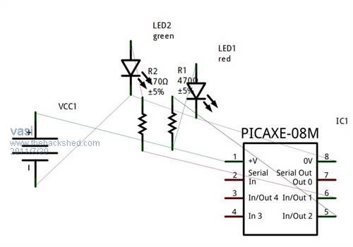
It is a little tricky but you can manage to get what you want (as I said earlier, you can skip this part if you don't need to present your schematic, or have a better tool for this): 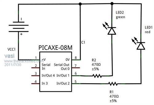
The same thing applies for the PCB (if you want to have a final PCB for your project). components are placed o a large board and you must resize it and make your traces: 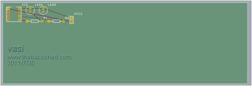
On "View" menu, you can find options for setting the grid and align to it. Drawing traces, is as tricky as in schematic editor but at the end you can make a nice PCB. It is helpful to activate the "Layers" panel from "Window" menu. Anyway, I didn't explored all features... 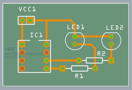
The good news for PICAXE users is that Fritzing have a programing window which is supposed to program your chip. Didn't explored this, I fried my PICAXE 08M long ago (about this, read below): 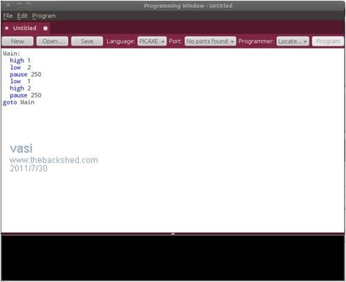
This is the result: http://www.youtube.com/watch?v=kstfZpydbjY I used a PC power source - be careful at connections, better use diodes to protect the chip if you reverse the polarity. ----------------- Note: This post wasn't intended as a true tutorial but only as an illustration of what can be done (well, a small part from what the program can do). Also, as I said, I didn't had a PICAXE but I used a 12F629 chip, along with my Pickit 2 programer and his testing board: The program was written in Oshonsoft Basic. Hobbit name: Togo Toadfoot of Frogmorton Elvish name: Mablung Miriel Beyound Arduino Lang |
||||
| vasi Guru Joined: 23/03/2007 Location: RomaniaPosts: 1697 |
Hi Ray, Is about the veroboard feature on Fritzing, where we don't have transparent components and you can't see what is under them and for this, we have another free program, not as good as Fritzting but very good on this particular area, Soon, I hope... Hobbit name: Togo Toadfoot of Frogmorton Elvish name: Mablung Miriel Beyound Arduino Lang |
||||
| vasi Guru Joined: 23/03/2007 Location: RomaniaPosts: 1697 |
I saw few Veroboard designers but what have Fritzing as a plus, is the possibility to verify your project against a schematic and this way, wrong connections are avoided. On Abacom LochMaster 4 is a way to highlight an entire node of connections to show what is connected to what but this don't help you so much. LochMaster have the most pleasant graphical representation of a veroboard but this program cost money and, if the board is overpopulated, things are hard to distinguish. Anyway, is not the one I wanted to discuss. Hobbit name: Togo Toadfoot of Frogmorton Elvish name: Mablung Miriel Beyound Arduino Lang |
||||
| vasi Guru Joined: 23/03/2007 Location: RomaniaPosts: 1697 |
I found the way to see the veroboard cuts on Fritzing and is related to layers: 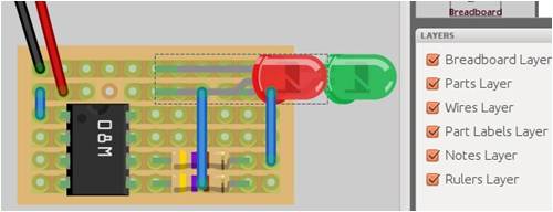
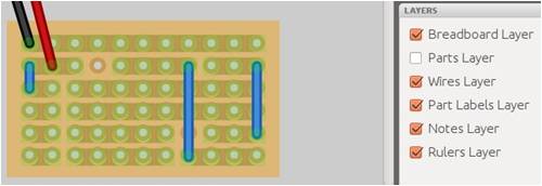
As you can see, in this area Fritzing still has a lot to do (veroboards and perfboards were added recently). First, it doesn't have yet the proper graphical components for these kind of boards. Second, it has problems in drawing the board at small dimensions (look at the offset on the strips from the bottom of the board). But is still great because any modification you make on veroboard, is automatically reflected on schematic so you can check your work at every step. No other program can give you such a feature (or I don't know about). Hobbit name: Togo Toadfoot of Frogmorton Elvish name: Mablung Miriel Beyound Arduino Lang |
||||
| vasi Guru Joined: 23/03/2007 Location: RomaniaPosts: 1697 |
Ok, the program is named DIY Layout Creator, v.3.0.8, by Branislav Stojkovic. The program is open source and is written in Java so, is multiplatform. Download the archive from here. For Windows you have an executable and for Linux/Mac OS X/UNIX, you have a .jar file which can be launched from a terminal window as this: [code] java -jar diylc.jar [/code] The program have 5 types of boards and once you placed the selected one, you can resize it by click&drag or edit it's attributes with Ctrl+E combination. Every component can be transparent, even the board. 
Here, the board have 77% opacity, making the sketch more readable: 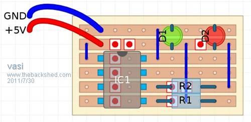
Two annoying things I found on the program: - the cut symbol (that rectangle with a red full circle in the middle); - initially, the cursor is in select mode. After selecting a component from the palette, the cursor enter in edit mode. It switches back on select mode after you placed the component so, if you place the same type of component in another place, you must first click again on the corresponding tool button. annoying. Some components as IC's and transistors have a default dimension, orientation and transparency. You can't change these before placing the component so, jut place it. Then, when it is still selected, press Ctrl+E combination and you can change what you want (and reposition the component if is required). Every component and wire can be edited with Ctrl+E. I like the way boards are looking. You can have also a B.O.M. list. But don't forget that this is just a drawing program, without schematic capabilities so, check carefully your design. Hobbit name: Togo Toadfoot of Frogmorton Elvish name: Mablung Miriel Beyound Arduino Lang |
||||
| Ray B Senior Member Joined: 16/02/2007 Location: AustraliaPosts: 219 |
Developments are sure moving on from VeeCAD for veroboard. Thanks again Vasi for the finds. RayB from Perth WA |
||||
| vasi Guru Joined: 23/03/2007 Location: RomaniaPosts: 1697 |
Working with DIY Layout Creator I found a limit at a maximum of 32 pins for a DIP IC. The workaround is to use two ICs with 20 pins and 0.6in spacing to simulate a 40pin DIP microcontroller: 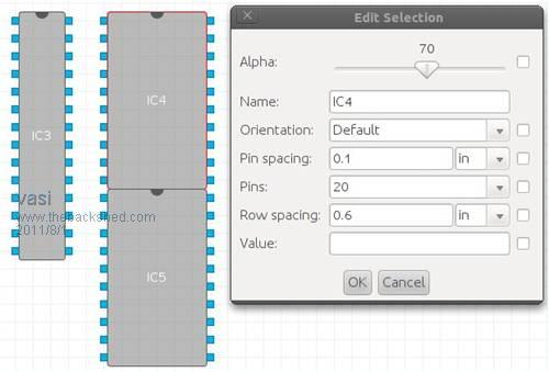
If the black line from the middle of DIP capsule interfere with your design (a resistor, wire, cut or jumper is placed there and you can't see details) then chose other combinations, an extreme one having 32 + 8 pins. Hobbit name: Togo Toadfoot of Frogmorton Elvish name: Mablung Miriel Beyound Arduino Lang |
||||
| vasi Guru Joined: 23/03/2007 Location: RomaniaPosts: 1697 |
This time, I used DIY Layout Creator 3.28 to remake the Glenn's Veroboard Wind/Solar Charger. Apart from the sources, there is also a generated .pdf file which can be zoomed at up to 800% (at least, with the viewer I have on Linux) and you can see all the details. I checked all the connections but I advise any who wants to try it, to check it again. Inside is Glenn's diagram to check against. 2014-05-25_140553_Vero.zip Hobbit name: Togo Toadfoot of Frogmorton Elvish name: Mablung Miriel Beyound Arduino Lang |
||||
| robert.rozee Guru Joined: 31/12/2012 Location: New ZealandPosts: 2350 |
with DIY Layout Creator it would certainly be nice to make the breaks in veroboard tracks appear round - i use a drill bit in a handle to break tracks. have you found any way to persuade it to produce an image of just the piece of veroboard (ie, components hidden) and mirrored? this to provide a guide for cutting tracks. rob :-) |
||||
| vasi Guru Joined: 23/03/2007 Location: RomaniaPosts: 1697 |
Well, only this way: It has a Layers menu, where you can select "en mass" components, solder points, etc. You save the project under a suggestive name, then select all components and solder points and then cut them and save the board with only the cuts. Then, you can print it reversed (wasting paper, ink or toner) or export it as a .png image and then flip it. So is possible, but a little more work to do. 2014-05-25_194410_windmill-controller-production-files.zip Hobbit name: Togo Toadfoot of Frogmorton Elvish name: Mablung Miriel Beyound Arduino Lang |
||||