Notice. New forum software under development. It's going to miss a few functions and look a bit ugly for a while, but I'm working on it full time now as the old forum was too unstable. Couple days, all good. If you notice any issues, please contact me.
Volhout Guru Joined: 05/03/2018 Location: NetherlandsPosts: 6151
Posted: 08:21am 01 Oct 2026
Copy link to clipboard
Print this post
A very simple solution (that is virtually impossible with drilling) is to screw the self threading screw into a square hole. A 3D printer can create square holes easily, and it is the simplest geometrical form that allows disposal of scraped off material.
Mixtel90 Guru Joined: 05/10/2019 Location: United KingdomPosts: 9167
Posted: 09:53am 01 Oct 2026
Copy link to clipboard
Print this post
That's a good idea. I might give that a try.
The little brass inserts hardly break the bank though. About £2 for 50 M3 or 100 M2.5. The attachment for a T12 iron was about £4.60. That deals with all sizes from M2 to M6. They are a much better idea for holding case halves together.Mick
Chopperp Guru Joined: 03/01/2018 Location: AustraliaPosts: 1139
Posted: 08:22am 03 Oct 2026
Copy link to clipboard
Print this post
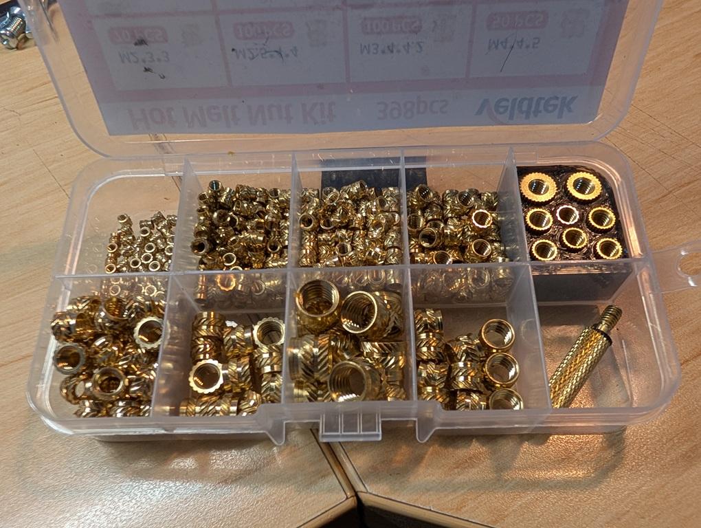
I didn't know about these. For bigger stuff, I've been using helical ones used in woodwork. They were sort of OK in part. I ordered a box of assorted heated ones which arrived today. They look much better & should work better assuming I can fit them properly. The 2mm ones look like fun. Thanks for that to others for their comments
BrianChopperP
Mixtel90 Guru Joined: 05/10/2019 Location: United KingdomPosts: 9167
Posted: 09:48am 03 Oct 2026
Copy link to clipboard
Print this post
Be careful with the inserts. There are single and double ended ones. The single ended ones are a simple tube at the end that enters the plastic and these are the ones we want. The double ended ones have knurled collars at both ends and are intended for injection moulding. I'm told that they will work but aren't as good, being difficult to insert and having less grip. I've not verified this.Mick
Chopperp Guru Joined: 03/01/2018 Location: AustraliaPosts: 1139
Posted: 11:09am 03 Oct 2026
Copy link to clipboard
Print this post
Thanks Mick
The ones I got are labeled as a Hot Melt Nut Kit & are single ended with the Chevron pattern on the top section a small plain section on the bottom. They came with the insertion tool & adaptors (which will be the first things to lose)
BrianChopperP
Mixtel90 Guru Joined: 05/10/2019 Location: United KingdomPosts: 9167
Posted: 11:18am 03 Oct 2026
Copy link to clipboard
Print this post
Yeah... The adapters are a bit small. :) They are made so that they can roll to inaccessible places too.
I bet there's a 3D printable holder for them somewhere.Mick
Chopperp Guru Joined: 03/01/2018 Location: AustraliaPosts: 1139
Posted: 11:49am 03 Oct 2026
Copy link to clipboard
Print this post
Now that's an idea. I made one for a set of wad punches many years ago so I wouldn't lose them. Now I can't find it or the punches.ChopperP
wjrii Newbie Joined: 03/10/2026 Location: United StatesPosts: 2
Posted: 01:43am 04 Oct 2026
Copy link to clipboard
Print this post
Hi all! Total newbie here to MMBasic, but twenty or thirty years ago I noodled around with QBasic some, and years before that Atari Basic on an XEGS. I've been playing around with Picos and 3D printing for a bit in the last couple of years. I mostly use them to make my own custom USB keyboards.
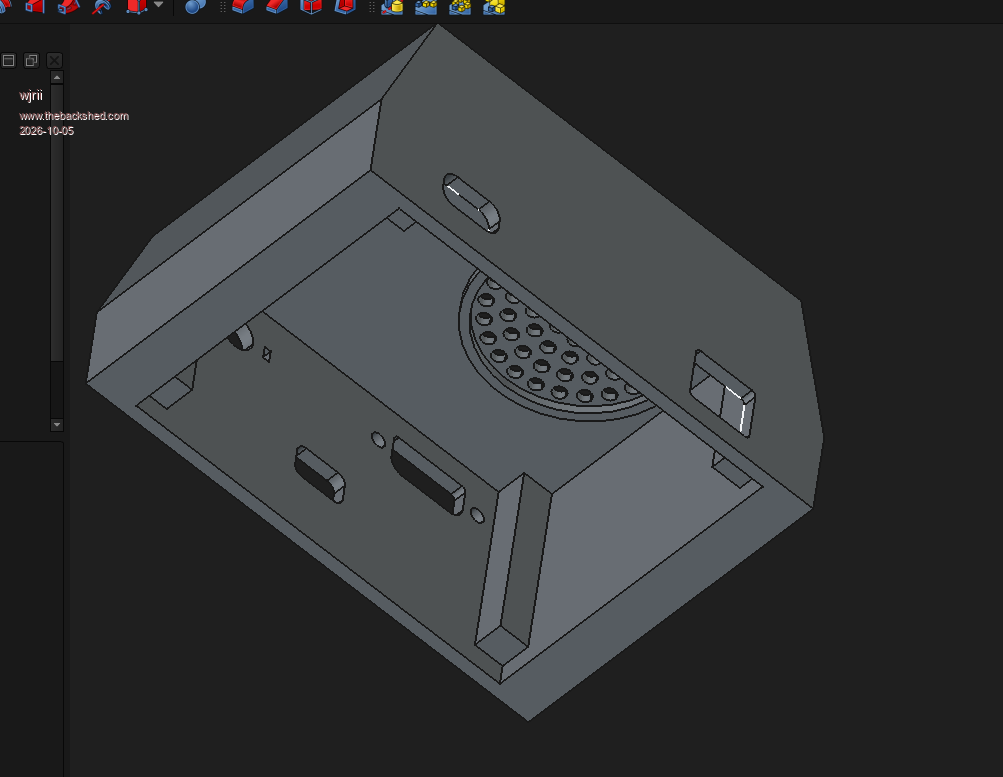
For my PicoMite VGA I used a 90x70mm perfboard and designed an open-bottom case in FreeCAD for it, as well as the LM386 amplifier and 40mm speaker I used with it. I printed the whole thing upside down and set my slicer to print the "top" 4mm completely solid. This gave me plenty of material to drill into but left the infill areas nearby to sort of "absorb" the deformation from screwing the board down.
For my keyboards I do generally use the heat-set inserts. You need to be quick and steady to use them on PLA, but I generally find them the best balance of simplicity and robustness.
As an aside, if you can wrap your head around the "sketch->extrude->sketch->pocket" workflow in one of the more advanced MCAD suites, I think you'll fairly quickly find it's much nicer than TinkerCAD, and almost as intuitive. Still, TinkerCAD is uniquely accessible and gets the job done for the most part, especially for enclosures.
Mixtel90 Guru Joined: 05/10/2019 Location: United KingdomPosts: 9167
Posted: 07:23am 04 Oct 2026
Copy link to clipboard
Print this post
Hi wjrii, and welcome to the shed. :)
I have a sort of "enclosure kit" in Tinkercad now. Ok, it's not parametric in the least, but it gives a way of making enclosures with front and rear panels in any size that I can handle. It's way slower than parametric but Hey, I'm retired, time isn't money now!
Getting rounded corners on an enclosure in Tinkercad is interesting. You can't stretch a cube without distorting the curves as the stretch is linear along the full dimension. I discovered that someone had found a way to solve it though. Little things like that, from an enormous user base, help a lot.
I sort of liked FreeCAD. Unfortunately I discovered that unless you can find newbie demos that are for *exactly* the version you have loaded then they can't be followed - a very minor difference in version number sees to that. I've seen other demos now and it looks rather good, but I'd already taken it off.
Chopperp Guru Joined: 03/01/2018 Location: AustraliaPosts: 1139
Posted: 07:27am 04 Oct 2026
Copy link to clipboard
Print this post
Well I couldn't resist so I designed & printed a holder to fit in my box of inserts. Had 4 goes. First was a tad small overall & I forgot that my setup prints holes about 1mm undersize. Added 1mm to all & that worked for the inserts. I had a hole for a 4mm insert so I could screw the long adaptor in & lift the lot out. That worked well.
The base was only about 5mm high with 4mm deep holes & I had the adaptors the other way up, smallend up. I decided they would be better with the threaded end up so I printed the one shown which is 13mm high with about 11mm deep holes.
I can screw the long adaptor into the bit I require or into the 4mm nut & lift the lot up being careful not to let any fall out.
BTW, I use OpenSCAD. I can't get my head around the other types.
@wjrii. Welcome to the forum.
EDIT. Didn't see Micks post above
Brian
Edited 2026-10-04 17:31 by ChopperpChopperP
wjrii Newbie Joined: 03/10/2026 Location: United StatesPosts: 2
Posted: 12:59am 05 Oct 2026
Copy link to clipboard
Print this post
If it works, it works, and the upfront investment of time to learn something new that you don't intend to become a hobby in its own right is a a non-trivial factor. Interesting and very cool that you have found a way that works for you to round the box corners. Fillets and Chamfers were what finally spurred me off TinkerCAD towards a parametric solution.
Speaking of, I don't actually use FreeCAD for most things, both for the reasona you mentioned and because the nature of the project means it's a bit behind in some areas and needs to be all things to all users. It was finally close enough in workflow to my normal suite (Alibre Design) that I didn't bother rebooting to windows for this relatively quick design. If you're still on Windows, Fusion360 is a good choice for as long as their free tier is usable, and it's definitely a more mature program than FreeCAD.
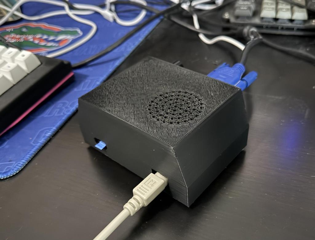
Here is my case, and while the top doesn't look quite so bad as that (my phone thinks we want to see every single imperfection), it would get a few changes if I were to print another. My 'Mite itself is a study in how many shortcuts and cheap-outs one man can take and still have it work. I didn't have any level-shifters or Mosfets on-hand, so we'll see how long my YD-RP2040 lasts with a single diode shielding its clock pin from 5v. I also skipped the filter circuit on the audio on the assumption that my little amp board could do the job. Finally, my VGA resistors are not quite perfect, but apart from skewing half a shade towards green, all seems well. This is what happens when you let a person with a literature degree own a soldering iron.

 Notice. New forum software under development. It's going to miss a few functions and look a bit ugly for a while, but I'm working on it full time now as the old forum was too unstable. Couple days, all good. If you notice any issues, please contact me.


 Print this post