
|
|
Forum Index : Microcontroller and PC projects : GAP2 Construction pack
| Author | Message | ||||
| Mixtel90 Guru Joined: 05/10/2019 Location: United KingdomPosts: 8912 |
Slight changes and a couple of fixes (sorry lizby!). The manual is enlightening. Once again, this is a design and it hasn't been built yet - you are more or less on your own. :) A little HDMI / USB / PS2 machine to use the WeAct Studios module, preferably with a PSRAM soldered onto it. I have one now and it appears to work. :) I don't think this will be difficult for most people to build if you ignore the PSRAM.  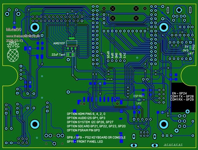 GAP2 construction pack.zip . Mick Zilog Inside! nascom.info for Nascom & Gemini Preliminary MMBasic docs & my PCB designs |
||||
| lizby Guru Joined: 17/05/2016 Location: United StatesPosts: 3787 |
Nice update, Mick PicoMite, Armmite F4, SensorKits, MMBasic Hardware, Games, etc. on FOTS |
||||
| Mixtel90 Guru Joined: 05/10/2019 Location: United KingdomPosts: 8912 |
I had a thought. Like you do at 03:30 AM. Why not expand the GAP2? It's got a nice polarised GPIO port that was designed for 26-way ribbon cable and IDC connectors. So a thing came to be thought of - the GAP D-POD. It's not often that I make one of my designs obsolete before I release the gerbers, but this might replace GAP1. 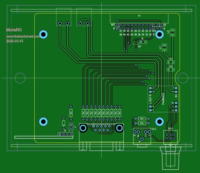 It has an identical D connector for controllers as GAP1 and also includes a power amp for external speakers, as GAP2 only supports headphones. It doesn't have the pretty LEDs as the case isn't clear, but my idea is to split the front panel and have a translucent section at one end with the LEDs behind that! They will just be driven from a different GPIO, that's all. Mechanically it's an identical enclosure with a short ribbon cable to link the two. You just stack them up. It's neat because, if you want the GPIO for something else just unplug it. Power is provided from GAP2, of course. A second idea closely followed the first... I know some of you can't get enough WS2812B LEDs so GAP LEDA. No design yet, but this is the idea: It has a power input at 19V 3A from a laptop supply. This feeds a 5V switcher that goes back to GAP2 to power it. When the 3V3 supply comes back it enables six 5V 1.5A supplies with diodes on the outputs. These are for powering strips, or part way along strips. Each has a voltage sense wire so that the 5V is at the remote end. There are also 3 serial data lines from the GAP2 and a link system that allows data out from a string to feed data in to a different string rather than it use a data line. If 6 supplies is a bit cramped I suppose it could be three 3A supplies. This would power rather a lot of WS2812B chips, even at full white output. I make it 150. A lot more for typical use. The three data lines don't conflict with the D-POD if you disconnect a jumper in there to disable its LED panel. I really shouldn't wake up at stupid o'clock. :( Mick Zilog Inside! nascom.info for Nascom & Gemini Preliminary MMBasic docs & my PCB designs |
||||
| The Back Shed's forum code is written, and hosted, in Australia. | © JAQ Software 2026 |
