|

|
Forum Index : Microcontroller and PC projects : LM135 temperature sensor interfacing
| Author | Message | ||||
| Bizzie Senior Member Joined: 06/07/2014 Location: AustraliaPosts: 191 |
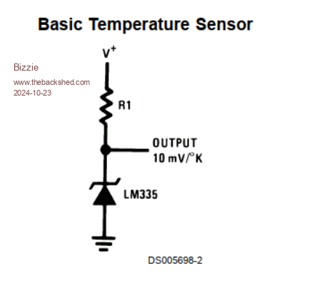
Hi all, Had a request from my son, Dad can you make me some probes to measure temperature inside or should I say inbetween round bales in the hayshed ASAP. I did not have any HTU21D's at hand so looked in the Jaycar catelogue and found my local store had some LM335's so went and bought 4. I started to build a board with a 28 pin MicroMite with a 12k resisor as the datasheet indicated. During testing of the board I relised the MM would see 12v! if no sensor was connected or the sensor went open circuit. See below example circuit.  Has anyone used these safely? I can not use the HTU21D's as the sensor is on the end of 12m leads and works perfectly doing manual measurements. Edited 2024-10-23 08:23 by Bizzie Rob White |
||||
| Andy-g0poy Regular Member Joined: 07/03/2023 Location: United KingdomPosts: 56 |
You have a few options: 1. a simple potential divider from the output to ground, Say 10:1 ratio and then scale up the readings in software, 2. Feed the input into an op-amp set up as a buffer, with its supply at 3.2V Then if the input every goes higher then the output will just sit at the supply rail. 3. Looking at the cct, it's a zener, so maybe a 3V zener at the MCU end to conduct if the voltage ever goes above 3v. I'm not sure how much that would affect the readings, depending on how high they get. Andy |
||||
TassyJim Guru Joined: 07/08/2011 Location: AustraliaPosts: 6091 |
Surely the maximum temperature in the hay is going to be above 57 degrees? 57 degrees C = 330 degrees K = 3.3V 3.3V is the max that the micro can handle with analogue inputs so you are going to need some sort of preconditioning anyway. I did use them in a hot house but found it reached the max too often. Jim edit: the DS18B20 would be my preference and it reads up to 125 degrees C Edited 2024-10-23 08:45 by TassyJim VK7JH MMedit MMBasic Help |
||||
| phil99 Guru Joined: 11/02/2018 Location: AustraliaPosts: 2131 |
+1 However as you already have the LM335s a 2:1 voltage divider across the LM335 (2 x 33kΩ perhaps) with a Schottky diode from AIN to +3.3V for open circuit protection. Option 2. Replace R1 with a 1mA current source fed from 5V to 6.6V and once again a 2:1 divider. I will draw it up and add it later. |
||||
| Bizzie Senior Member Joined: 06/07/2014 Location: AustraliaPosts: 191 |
Thanks for all your quick replys as usual. Will use the voltage divider and software like the kiss principle. Rob White |
||||
| phil99 Guru Joined: 11/02/2018 Location: AustraliaPosts: 2131 |
If using just the divider errors are scaled up by the ratio so 4:1 would be better than 10:1 yet still give protection from 12V. |
||||
| Bizzie Senior Member Joined: 06/07/2014 Location: AustraliaPosts: 191 |
Yep thanks, I only need to start worring when bales get above ambient by say 5 degrees. Rob White |
||||
TassyJim Guru Joined: 07/08/2011 Location: AustraliaPosts: 6091 |
If you are only interested in reading up to 57 deg, I would run without any voltage divided and a Schottky diode from AIN to +3.3V If you want higher, a 2:1 divider and keep the diode. Using too high a divider will loose reading accuracy. I am not sure where you are so ambient could be anywhere from 0 to 50+ Jim where today is a pleasant 18 degrees. VK7JH MMedit MMBasic Help |
||||
| phil99 Guru Joined: 11/02/2018 Location: AustraliaPosts: 2131 |
Looked up "haystack temperature". It's complicated so simple summary:- To limit degradation of protein the temp should be limited to 55°C. To prevent fire temp. can be much higher, see this. Haystack Fires |
||||
| Bizzie Senior Member Joined: 06/07/2014 Location: AustraliaPosts: 191 |
Thanks Phil that will provide some hours reading! Jim I am nowhere near up to speed on the subject as proven with Phil's link! If you look at table 5 (the good old crow bar test) in that link up to 60 + degrees is required. Thanks all for your interest. Rob White |
||||
| Mixtel90 Guru Joined: 05/10/2019 Location: United KingdomPosts: 6761 |
Another rather nice device is the MCP9701A active thermistor, but max limit on that is also 125°C. That one is 19.5mV/°C and is designed for microcontrollers, but there is also the MCP9700A which is 10mV/°C. These are linearised up to 70°C. Generally to go higher than 125°C you have to have thermocouples as you are reaching the physical limits of silicon-based sensors. That involves using a thermocouple amplifier to get the voltage that you want. Type K thermocouples are probably the easiest and cheapest to use. Mick Zilog Inside! nascom.info for Nascom & Gemini Preliminary MMBasic docs & my PCB designs |
||||
| CaptainBoing Guru Joined: 07/09/2016 Location: United KingdomPosts: 2074 |
consider a simple thermisor setup very cheap, "programmable" to any reasonable temperature range and quite accurate. You can easily run it from 3.3V as it is a purely resitive device so that eliminates an over-voltage worries. I did this for my 3D primnter heated bed and it is very trustworty and just works. You could easily make up you own probes - two wires to a thermistor and back to the uC and all the "gubbins" there - you could have many of them (as many as you have AIN pins) and it's just a bit of maths in the software. That's the way I would in this instance. |
||||
| Mixtel90 Guru Joined: 05/10/2019 Location: United KingdomPosts: 6761 |
You can also measure Vf of a silicon diode. It works rather well. I've done that using a PIC chip. The limit of 125°C for anything involving silicon is because it stops working as a semiconductor at around 150°C. Linearity has often gone to pot before you get that high anyway. ---- The LM335 does *not* require 12V or a 12K resistor. The resistor value is chosen to put between 400µA and 5mA through the LM335 at the voltage and temperature you are using. The maximum voltage is 3.3V for the Micromite (limited by the ADC input). At 3.3V the maximum temperature you can read is a bit less than 57°C. The maximum value for the resistor at this voltage has to be less than 384Ω. Reference Mick Zilog Inside! nascom.info for Nascom & Gemini Preliminary MMBasic docs & my PCB designs |
||||
| Bizzie Senior Member Joined: 06/07/2014 Location: AustraliaPosts: 191 |
I am now confused, if I go the thermistor route what resistance value should I choose? Jaycar lists 8 various resistance devices from 15Ω to 100k. What sort of milli/micro amperage range should I be aiming for? Edited 2024-10-24 11:20 by Bizzie Rob White |
||||
| phil99 Guru Joined: 11/02/2018 Location: AustraliaPosts: 2131 |
The nominal published resistance is usually measured at 25°C and it falls at the temperature rises. As you normally use the thermistor as one leg of a voltage divider, you choose the other resistance to get around Vdd / 2 at the temperature of greatest interest. As you are interested in higher temperatures a 10kΩ or greater would be suitable. For measuring temp. you want to keep the current low to prevent self heating affecting the measurement. On AliExpress you can find them already sealed in a probe with cable. One catch is Jaycar and many other sellers don't publish the Beta value of their thermistors. Beta is vital for calculating the temperature from the measured resistance. By tedious calibration I found a Beta of 4300 works for the Jaycar ones over the range 15 to 90°C. Beyond that range accuracy decreases. Outside that range calibration is needed to get a Beta that works for the range you require. The maximum temp. for the Jaycar ones is 125°C, probably due to the resin encapsulation. In short unless you really need to read higher temperatures stick with what you have, it's already calibrated. Edit the 100kΩ glass encapsulated one is rated to 250°, but will probably need calibration to use that range. Example code Vin = Cint(Pin(GP26)*1000) / 1000 'analogue input, remove excess digits Ra = R1 * Vin / (3.3 - Vin ) ' Calc. resistance, R1 = series resistor, ohms. Temp = 1/(1/(T0+273.15) + Log(Ra/R0)/beta)-273.15 Calc. temperature ' R0 = resistance (ohms) at reference temp, T0 (25C) Temp = Cint(Temp*100)*0.01 'remove excess digits Edited 2024-10-24 15:35 by phil99 |
||||
| CaptainBoing Guru Joined: 07/09/2016 Location: United KingdomPosts: 2074 |
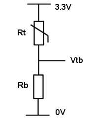
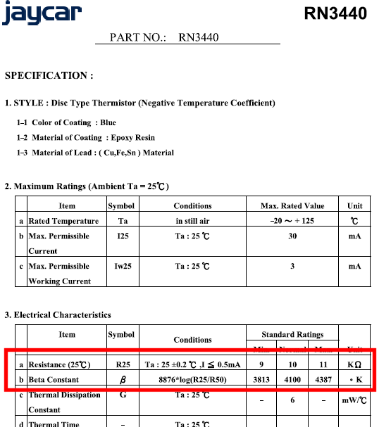
Hey Bizzie. Don't worry about current, you're going into a Hi-Z AIN and a KΩ+ resistor... thermistors play nice as part of a potential divider so it's just volts and ohms at the values we are using. as @phill99 pointed out you need to know two things about your thermister: 1.Most thermistor resistances are stated as they are measured at 25°C - obvioulsy resistance changes with temperature so 25 was adopted as a fixed point in the range. Try to get one around R25=10KΩ 2. you'll need to know its "Beta" - don't worry too much about this, it's the fall-out of an equation and allows you to estimate the °/Ω curve without some horrible complex maths, good enough for most applications. Every supplier will show this in the datasheet. So, considering the following measurement circuit (only the thermistor is exposed to heat)...  ... When I was playing with them, I found the following: trying to get Vtb=1.65V, i.e. middle of the voltage range (and so Rt=Rb - a straightforward 50/50 divider) with Rb=1K, Temp was 83°C with Rb=2K2, Temp was 59°C and with Rb=4K7, Temp was 39°C In your place (and assuming you have the same Beta - or near it) I would go for Rb=2.2K. This means that when you get 1.65V at Vtb, the thermistor is ≈59°C. Here's a little prog I wrote ages back when I was playing - it helped me visualize things a bit better (with added comments)  It runs this morning on a MicroMite 28 pin jobby Dim Float R25=10000,Beta=3950,Vcc=3.29,Vtb,Rb,Rt,tmpC,x Const TRm=25+273.15 Print "*****************************" Print "* Thermistor calculator *" Print "*****************************" Print "Enter Vcc [";Vcc;"]";:Input "",x ' Supply voltage if x<>0 then Vcc=x Print "Enter Beta [";Beta;"]";:Input "",x ' Beta of the thermistor if x<>0 then Beta=x Print "Enter R25 [";R25;"]";:Input "",x ' R25 of the thermistor in ohms if x<>0 then R25=x Input "Enter Rb ",Rb ' your balance resistor in ohms Input "Enter Vtb ",Vtb ' voltage on your AIN pin Print "-----------------------------" Rt=Rb*((Vcc/Vtb)-1) ' replace the line above with the following in your prog ' Rt=Rb*((Vcc/Pin(Vtb))-1) ' tmpC=((Beta*TRm)/(Beta+(TRm*Log(Rt/R25))))-273.15 Print "Temperature:";tmpC so looking at the datasheet for the JayCar part RN3440,  it looks ideal (R25=10K, Beta=4100). Grab a load and make up a loom with tons of these - 12m of wire won't significantly affect the resistance of the thermistor at these currents. Regardless of the LM335/Thermistor choice, you could have ten(!) sensors on a 28pin MM simple, analogue, robust & fixable/maintainable in a farm environment... you could have loads of them... a short PVC tube with the sensor in epoxy, the lead ending in a 3.5mm plug... Just stuff them in between the bales and run the lead to the controller and when they get squashed/severed, you just grab a new one, number it up accordingly and plug in. That's a fun project, and really useful for your boy. h Edited 2024-10-24 22:10 by CaptainBoing |
||||
| matherp Guru Joined: 11/12/2012 Location: United KingdomPosts: 9084 |
If you want to calculate thermistor temperatures properly then see here Summary: Get three temperature/resistance pairs from the datasheet Calculate the three Steinhart-Hart coefficients using the online calculator. You only need to do this once for any given thermistor type Insert the coefficients into the functions in the post to do the calcs accurately. |
||||