|

|
Forum Index : Other Stuff : Quadrature encoders
| Author | Message | ||||
| Gordz Regular Member Joined: 10/08/2013 Location: AustraliaPosts: 55 |
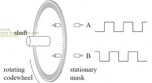
The most common type of quadrature encoder uses two output channels (A and B) to sense position. By using two sensors (often LED / PT combinations in optical versions) mounted 90 degrees out of phase, the two output channels of the quadrature encoder outputs a 2 bit representation of both position and direction of rotation. If A leads B, for example, the disk is rotating in a clockwise direction. If B leads A, then the disk is rotating in a counter-clockwise direction. The pulse duration gives an indication of speed. This means that by monitoring the number of pulses and the relative phase of signals A and B, you can track both the position and direction of rotation. Some quadrature encoders also include a third output channel, this is often called a zero, home or index signal, which supplies one single pulse per revolution. This single pulse is used for a precise determination of the reference position. Old ink jet printers are a great source for precision optical quadrature encoder sensors, disks and strips. 
|
||||
| Gizmo Admin Group Joined: 05/06/2004 Location: AustraliaPosts: 5078 |
Thanks for posting that Gordz. Another ( once ) common quadrature encoded was the good old serial mouse. It had 2 wheels. The on board chip would take the wheel positions, and periodically send the positions via the serial cable. The chip would store and track the positions until the next data transfer, so even if you moved the mouse quicker than the serial port could transfer the data, the positions would still be correct. I once wrote a VB program to use a old serial mouse as a linear encoder, using laser cut slots in a stip of plastic. It was part of a digitiser for CAD. Glenn The best time to plant a tree was twenty years ago, the second best time is right now. JAQ |
||||
| Gordz Regular Member Joined: 10/08/2013 Location: AustraliaPosts: 55 |
That was back in the day Glenn :) the new version just takes snapshots of the surface and compares subsequent pictures to calculate the direction and distance moved. Would be a great hack to use one for detecting changes in position of an object or even add a forum of intrusion detection with the right lens. I mentioned RS232 to someone the other day and all I got back was "what ?" |
||||
Prime_8 Regular Member Joined: 07/12/2014 Location: CanadaPosts: 51 |
holy hell , just got a look at this now . i was walking on one of my rounds about a hour ago wishing I had some of my old mice to 'chop' up . I remember cleaning those freaking ball mice. ? i was looking at some of the rotary encoders you can get off line . they look like rotary switches . I wonder if there are any i could just directly couple to a lead screw. Assuming there is no position 'click' . I know i could probably de-click them . but what a PITA that would be . I have a bunch of linear encoder / readers and the thin acetate strips from inkjet printer salvage . but i have a few of the opto pairs then read them . I think i might be able to rig a rotary on on the actual lead screw . it would be slower moving than my geared motors (servos) . I would love to figure out how MakeSmith guys used a chip to turn a magnet position to a PWM signal . i think it simply maps heading to the PWM scale of a servo . they drive their CNC by hobby servos . The servos i have left over from early R/C building days are much larger and full metal gears with Teflon? on final. of course i could make a position tracker on a nano , using its interrupts , have it track position and feed it much as the old serial mouse would, except on I2C buss. or wait for my Mega as i think it has more interrupts . Old coder, and bodger of things that may spark. |
||||
| powerednut Senior Member Joined: 09/12/2009 Location: AustraliaPosts: 221 |
the chip was probably a hall effect sensor. |
||||
Prime_8 Regular Member Joined: 07/12/2014 Location: CanadaPosts: 51 |
yeah , i think so it converted rotation of a magnet into deg , then to PWM . I will go check their forums tonight as they have made mention of selling their sensors too . a 3 axis magnetometer is over kill but some are so cheap and have I2C . BUT most i can pus my I2C is 400khz( i forget , but default is only 100 ) in the mean time i found these ones , i may just scoop a couple if i order some other bits and bobs . i need a few darlington arrays ( I forget chip id ) http://www.ebay.com/itm/Photoelectric-Speed-Sensor-Encoder-C oded-Disc-code-wheel-Freescale-Smart-car-/400566013021?pt=LH _DefaultDomain_0&hash=item5d43984c5d thing is think i have 3 of those sensors , but with other disk patterns . after watching a video about using ASM functions on Arduino for fast pin mode switching to get more interrupts , I might just use something like this for 3 axis . ~ but yeah i think one HE sensor could be made to produce a PWM , or just go rite to a analog pin . I see they use a MEGA , and those guys have 6 interrupts , and many analog pins too . Thanks BTW . Old coder, and bodger of things that may spark. |
||||