
|

|
Forum Index : Other Stuff : axial flux FEMM animation
| Page 1 of 3 |
|||||
| Author | Message | ||||
| Dinges Senior Member Joined: 04/01/2008 Location: AlbaniaPosts: 510 |
So I've been playing with FEMM a little more. Decided to make an animation of the changing magnetic fieldlines as a function of airgap for the axial flux generators. A small, low-resolution sample is shown below. Even this one clearly shows the changing flux lines and increasing leakage flux and diminishing flux density as the airgap increases. 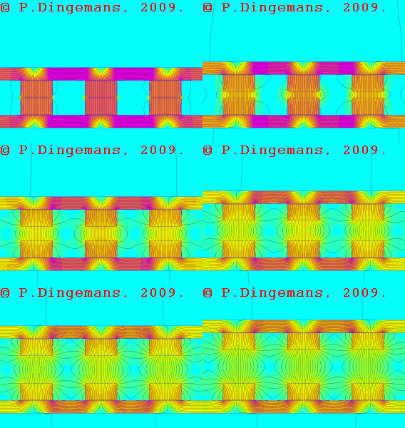
Links to the complete animations can be found below. I like the 2nd one better because of the absence of a sudden transition in the loop, but the price for that is a much larger file. Click on the magnifying glass (near top-right of the image) to start loading the file and viewing the animation. http://picasaweb.google.com/motorconversion/AxialFluxFEMMSim ulations#5288197761856843090 (warning, 7MB filesize) http://picasaweb.google.com/motorconversion/AxialFluxFEMMSim ulations#5288199885557074706 (warning, 15MB filesize) The technical details of the generator are: steel plates 10mm thick AISI-1010. Magnets N40 2"x1"x.5", viewed 'head on' (2" dimension into the screen). Spacing between magnets is 25mm (one magnet width). Minimum airgap 1mm, maximum airgap 27mm. Hopefully others in this forum will find these animations useful too in visualizing and understanding the magnetic fields of axial flux generators. Peter. |
||||
oztules Guru Joined: 26/07/2007 Location: AustraliaPosts: 1686 |
Very very nice Mr Dingesman. It is nice to see that there is a reasonable winding window there for good flux, wire room and mechanical strength. A well spent 15mb of bandwidth. I have henceforth stolen a copy as a reference for my next supergenerator. It certainly is good to see what happens rather than guessing. Since you introduced me to your Femms, I can now pretty well guess what the fields will do and look like, but without your initial efforts to get me on track, I would never have gotten to that understanding...just couldn't get it. Thanks a bunch ........oztules Village idiot...or... just another hack out of his depth |
||||
| GWatPE Senior Member Joined: 01/09/2006 Location: AustraliaPosts: 2127 |
Hi dinges, nice work! Would have been good to have this sort of tool when I designed my AxFx motor, that I use for my AxFx mill. iron filings, and a hall effect sensor had to do, for me. Gordon. become more energy aware |
||||
| Dinges Senior Member Joined: 04/01/2008 Location: AlbaniaPosts: 510 |
Thanks, Oztules and Gordon. As I said, I hope it's of help to others for visualizing what normally remains invisible with these generators. It actually opened my eyes to something I hadn't fully realized myself yet. Took 6 hours of numbercrunching by the PC (P4/2.4GHz), but I figure the result is worth it. Peter. |
||||
wdyasq Newbie Joined: 29/07/2008 Location: United StatesPosts: 21 |
I hate it when I need to say nice things about a Dutchman. So, how many think he stole that file? Ron Adventure is just bad planning." -- Roald Amundsen |
||||
oztules Guru Joined: 26/07/2007 Location: AustraliaPosts: 1686 |
Ditto Ron.... I only said nice things in case I need a Femm done myself.... he knows I'm hopeless 
........oztules Village idiot...or... just another hack out of his depth |
||||
| philb Regular Member Joined: 05/07/2008 Location: United StatesPosts: 96 |
Thanks Peter, IMHO, it was worth 6 hours. The file is going into my archives. Visualizing the invisible is everything. Now I'm thinking about my last mill. Maybe the coils could have been a bit wider and thicker...hmmm. philb |
||||
| vawtman Senior Member Joined: 14/09/2006 Location: United StatesPosts: 146 |
Nice work Peter and thanks once again for your help with mine 
One can actually predict the future for a turbine with these simulations. |
||||
| Gizmo Admin Group Joined: 05/06/2004 Location: AustraliaPosts: 5078 |
So long as the magnet pole across the coil gap is closer than the neighboring magnets pole, most of the flux will go across the coil gap. A taller ( more distance between its poles ) magnet also will be more inclined to throw its flux across the coil gap, which is one reason 2 or more stacked magnets work better. I wonder what gain would be had if, instead of two stacked magnets, we used one magnet and one same sized block of steel under it. If it means it will throw ( for want of a better word ) its flux further, for little extra cost, it could be worth considering. Glenn The best time to plant a tree was twenty years ago, the second best time is right now. JAQ |
||||
| Dinges Senior Member Joined: 04/01/2008 Location: AlbaniaPosts: 510 |
Glenn, I think I know what you're getting at but if you could make a sketch of it I'll try to give simulating it a run. Now that the LUA script is working properly it has taken most of the hard work out of it. All that's left now is dumb work... In the mean time, to prove Ron wrong, I've made another one of the case without steel backing plates. It's interesting to see how, as airgap increases, the flux lines initially bend back to the same magnet (shorting over the outside of one magnet) but then later, as airgap becomes larger, start shorting to the neighbour magnets. It's also immediately obvious that the flux densities are much lower than the case with steel backing plates. 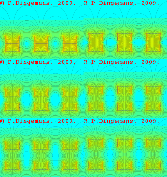
The detailed animation can be found here (warning, 19MB filesize): http://picasaweb.google.com/motorconversion/AxialFluxFEMMSim ulations#5288870849377406322 Peter. |
||||
| Gizmo Admin Group Joined: 05/06/2004 Location: AustraliaPosts: 5078 |
This is what I'm thinking. 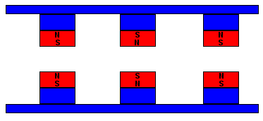
Each magnet is on a steel pillar, to lift it clear of the rotor plates. The magnet path through the steel rotor is still complete, if slightly longer. The hope is a larger gap could be achieved with the same flux density. It would be interresting to see what FEM has to say. If adding steel pillars means a increased flux density or increased air gap, than its a cheaper option that stacked magnets and better power than single magnets flat against the rotor face. See what I'm getting at. Glenn The best time to plant a tree was twenty years ago, the second best time is right now. JAQ |
||||
| whiskey Newbie Joined: 19/06/2007 Location: IrelandPosts: 21 |
Over the Christmas period I got called to a 6Kw Proven wind turbine installation that needed help. This is a down wind machine and relatively slow speed. The magnetic rotor was approx 2 1/2ft in diameter and its magnets were fixed horizontal, not vertical like most home brew wind turbines are built. The magnets were approx 150mm long and 50mm wide and 20mm deep. They may have been made by stacking two magnets together, evidence of some 'goop' was visible along the mid (10mm) point on the magnets. It has 12 poles (there was a surprise) and the coils were at embedded in a hard plastic like mouled material and was at least 50mm thick. The air gap was very wide, 5mm at least. I believe Proven use a Toroid type coil for high efficiency. I would agree with that arrangement if it were not for the pictures I have been sent of burnt out coils from their machines. Cooling may be a problem, or the blades may have a control problem. For those who want to research Toroids. have a looksee here http://hyperphysics.phy-astr.gsu.edu/Hbase/magnetic/toroid.h tml Some footage of the machine sitting on its shipping pallet exists and I will look into extracting some pictures of the magnetic rotor is any of you want to see it. Whiskey |
||||
| Dinges Senior Member Joined: 04/01/2008 Location: AlbaniaPosts: 510 |
(Ok, let's test the bandwidth of Glenn's new server with a few MB of animated GIFs  . Apologies in advance to users with low bandwidth connection). . Apologies in advance to users with low bandwidth connection).
Here are the final axial flux animations. I expect these will be the last I've made as I think all the basic variations on the theme are covered by now. I've run 5 extra cases. One where the return rotor is a flat plate, without any magnets on it. Next simulation is of a plain steel return plate but with 'dummy' steel blocks on them, the blocks having the same dimensions as the magnets. Then, an example of a triple-rotor axial flux, an idea one occasionally hears about. But I think the most interesting simulation is this one. Instead of varying airgap, I varied spacing between magnets whilst keeping airgap constant (at one magnet thickness, 12.7mm). The results seem to suggest that spacings above about one airgap wide seem to yield little to no benefit; as spacing is increased, the flux, instead of shorting to its neighbouring magnets, starts to fold back on its own magnet or steel rotor plate. Considering that 'normal' magnet spacing is considered to be about one magnet width (that would be 25mm in this case), there seems to be potential for improvement here in axial flux construction, at least from a magnetic point of view. It's similar to what Gordon did with his axial flux generator, where magnet spacing also was about the same as airgap. There's of course still the other matter that we need space for the coils, which also becomes smaller as magnet spacing decreases. But from a purely magnetic-circuit perspective, it makes little sense to have spacings much larger than the airgap, as there's no reward in more airgap flux: 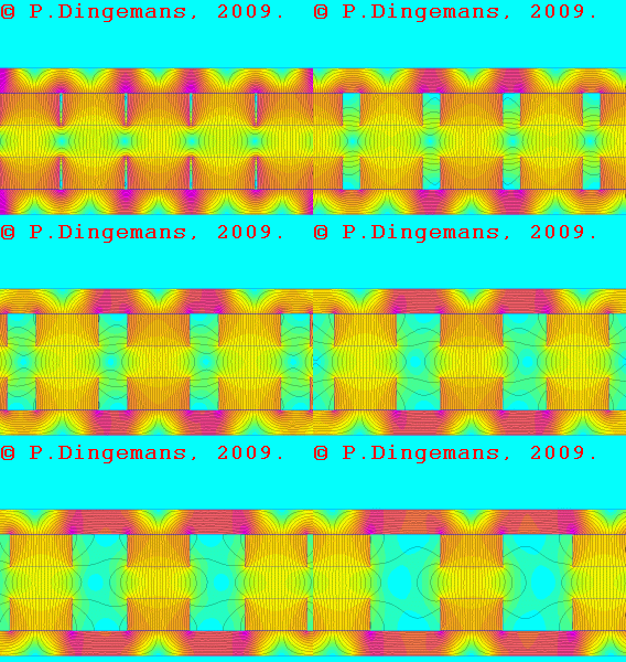
http://picasaweb.google.com/motorconversion/AxialFluxFEMMSim ulations#5289268036848722690 The other new animations: 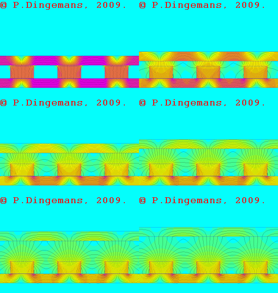
http://picasaweb.google.com/motorconversion/AxialFluxFEMMSim ulations#5288967311555894498 (Vawtman, the above case is nearly identical to your radial flux cartwheel generator) 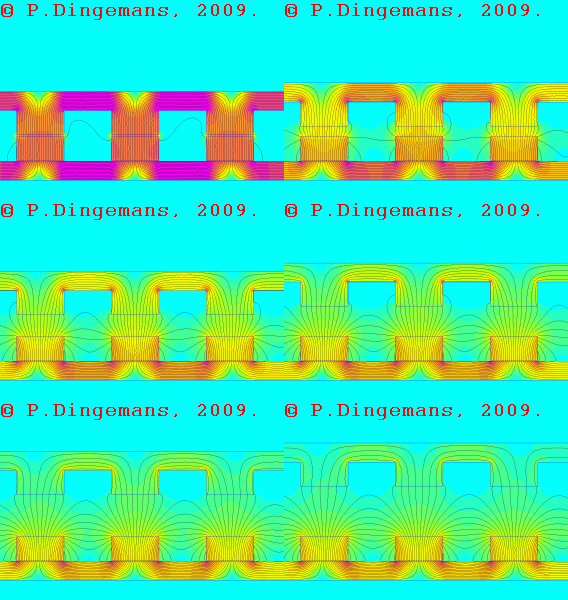
http://picasaweb.google.com/motorconversion/AxialFluxFEMMSim ulations#5289043782055815058 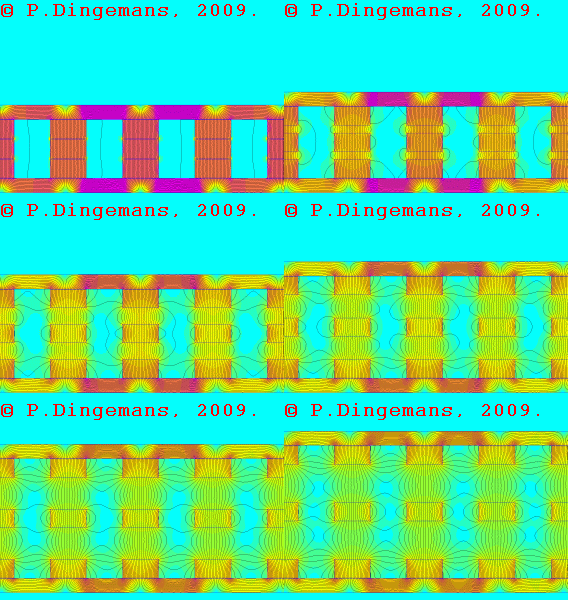
http://picasaweb.google.com/motorconversion/AxialFluxFEMMSim ulations#5289225266561397682 The final animation is of Gizmo's idea to mount the magnets elevated on protrusions: 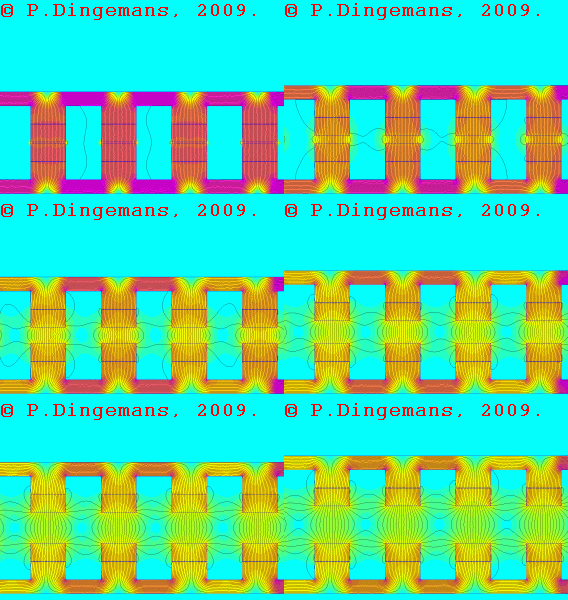
http://picasaweb.google.com/motorconversion/AxialFluxFEMMSim ulations#5289160456097816914 Glenn, as you can see, I ran the simulations and made a little animation of your idea to try to improve the axial flux. However, as the animation only shows the flow of the flux lines it's not easy to determine absolute value of flux densities to compare your design with the normal axial flux. So, I ran two more simulations (for the specific case of an airgap of exactly one magnet thickness, i.e. 12.7mm) to gather the hard numbers. As peak flux densities turned out to be exactly the same for both cases I did another check and integrated the flux (area of integration is 25mm wide and exactly halfway in the airgap). It turns out that even then there is no difference between the normal axial flux design and yours... Not what I intuitively expected (says more about my intuition than anything else, I suppose...). See numbers below: Normal axial flux generator: Average B.n = 0.67953 Tesla Gizmo's axial flux generator: Average B.n = 0.680348 Tesla Absolutely no difference between the two apart from noise. It looks like the conventional dual rotors (with magnets on both) are actually a pretty good design. One thing I've concluded from doing all these simulations and watching the animations is that it will take a pretty clever guy to make improvements to the magnetic circuit of the axial flux... One final disclaimer of all these simulations and animations: they're only an approximation of reality and don't take all factors into account. They basically show only the magnetic flux as it is when there is no generation going on. As soon as real generation starts, the coils create their own, counter-acting magnetic fields, which influences the magnetic field the permanent magnets generate, in essence 'pushing it back'. So, anyone reading this, keep that in mind when interpreting the simulations and drawing conclusions. They show only a fraction of what is really going on inside a generator. Consider it to be an approximation (at best). Peter. |
||||
oztules Guru Joined: 26/07/2007 Location: AustraliaPosts: 1686 |
[quote]But I think the most interesting simulation is this one. Instead of varying airgap, I varied spacing between magnets whilst keeping airgap constant (at one magnet thickness, 12.7mm). The results seem to suggest that spacings above about one airgap wide seem to yield little to no benefit; as spacing is increased, the flux, instead of shorting to its neighbouring magnets, starts to fold back on its own magnet or steel rotor plate. [/quote] In reality, it is more likely that the airgap for that magnet size will be 19mm. The stator would be 13mm min (strength and winding room) with perhaps a few mm either side. Using your analogy, that would put the inter magnet gap up to about .75 magnet width.... which is about the range I would expect.. (3/4 to 1 magnet width). Thanks once again for your tireless work in this femm business. ............oztules Village idiot...or... just another hack out of his depth |
||||
wdyasq Newbie Joined: 29/07/2008 Location: United StatesPosts: 21 |
It sure is nice when someone does work you have been wondering about. Thanks Peter. I have been contemplating a 'wave wound' axial flux alternator. This style of winding should give twice as many 'cuts' of the magnetic field as 'simple coils' and allow a thinner stator. This all should result in more voltage at lower speeds. I need to do some calculations as to proper magnet spacing. I plan on using the 1 x 2 x 1/2" magnets. the array of magnets that will give proper 'flux change' and sufficient capacity still needs to be 'guessed' and a prototype made. Peter's work has been inspiring. Some folks get so inspired they commit suicide. Ron Adventure is just bad planning." -- Roald Amundsen |
||||
| Dinges Senior Member Joined: 04/01/2008 Location: AlbaniaPosts: 510 |
[quote=Whiskey]The magnetic rotor was approx 2 1/2ft in diameter and its magnets were fixed horizontal, not vertical like most home brew wind turbines are built. The magnets were approx 150mm long and 50mm wide and 20mm deep.[/quote] Hm. That would be about 110 cubic inch of magnetic material?! That's a lot. Are they NdFeB or ceramic magnets? [quote=Whiskey]The air gap was very wide, 5mm at least.[/quote] For a 2.5ft (750mm) diameter rotor, I don't consider 5mm airgap to be excessive to provide the required mechanical clearance. Of course one could reduce it, but it'd require greater accuracy in machining and may turn out to be less reliable in the long term, when (not if) the bearings start wearing out. Especially in an environment where regular preventive maintenance isn't carried out (where is that done anyway... usually things get looked after when they have become defect and ignoring the situation is no longer an option). [quote=Whiskey]I will look into extracting some pictures of the magnetic rotor is any of you want to see it.[/quote] Of course we want to see it Whiskey... Any chance to get a closer look at a professionally built windturbine is welcome. [quote=Oztules]In reality, it is more likely that the airgap for that magnet size will be 19mm. The stator would be 13mm min (strength and winding room) with perhaps a few mm either side. Using your analogy, that would put the inter magnet gap up to about .75 magnet width.... which is about the range I would expect.. (3/4 to 1 magnet width). [/quote] I agree, the 12.7mm airgap is a bit on the smallish side when compared to current reality. The main reason for using an airgap equal to one magnet thickness in those simulations is for scaling and comparison purposes. However, I disagree with you where you state a magnet spacing in terms of magnet width (though I realize I've done the same myself... Hm.); it's more correct to state it in terms of (desired) airgap. When airgap varies, optimal magnet spacing varies too, more or less independent of magnet width. I think in this particular case I would settle myself for a spacing somewhere around 2/3 magnet width, which, if I'm not mistaken, is a tad closer than is commonly suggested. Resulting in more magnetic material in the generator for a same given physical dimension, thus resulting in a more powerful generator (and one with lower resistance; you'll love that part  ). ).
Ron, I'd suggest to put out your idea in the open for discussion and criticism, but your call. The more eyes have a look at it, the more relevant criticism you may receive. After all, it's possible that you (and I) have missed something. Unless you're too insecure for that, of course... 
BTW, have you ever considered a career in politics? Your natural ability for 'double speak' (where things can be interpreted in various ways, according to how each listener wants to interpret it) would render you a natural candidate for such a career. Because I'm still not sure whether your remark was a compliment or the opposite... 
Peter. |
||||
| whiskey Newbie Joined: 19/06/2007 Location: IrelandPosts: 21 |
Hi Peter, I have not worked out the magnetic area, but will trust your figures as a fellow engineering type :) The magnets are painted black and it is difficult to tell what material they are constructed with. If I had to guess I would think NdFeB and certainly lower than N40 grade. N35 would be closer in my opinion. A 5mm air gap to coil spacing in my experience is light years. I aim for 1mm most of the time and only wider on larger machines where there is less rotor support available. Some home builders like a wide air gap to help reduce or eliminate stall at higher wind speeds. I dislike to build a 90% efficient alternator and open up its air gap and reduce the efficiency due to poor blade design. The minimum air gap for maximum energy production is the aim of any alternator, and a blade must also be designed for the alternators power curve, or should be. CNC machining is a must for tighter tolerances and I am fortunate to have access to such machines. The Proven blades are something else, made from some plastic flexible material and does not instill confidence in me at all if I were an owner. The coils I think could be interesting if we could get a look inside the goop they are embedded in. Toroidal coils appear to be used and that is not a common way to wind coils for wind turbines. I have taken a movie of the machine and will see can I extract a few stills from it and post them here. With regards your comment on Ron, we all know he is really a yankie dressed up as a Texan and as such he has a way with words. Words to confuse, jest and offer sense. Having exchanged many chats with Ron on IRC I would qualify my statement of Ron and say he is one of the good guys. Sorry Ron, I know you said no agreeing, but the truth must be told ;) Whiskey |
||||
| vawtman Senior Member Joined: 14/09/2006 Location: United StatesPosts: 146 |
http://www.fieldlines.com/story/2007/11/25/18599/255Flux reply Peter the a.k.a cartwheel generator was never intended to be efficient 
What do you make of fluxs'comments ? |
||||
| Dinges Senior Member Joined: 04/01/2008 Location: AlbaniaPosts: 510 |
[quote=whiskey] Having exchanged many chats with Ron on IRC I would qualify my statement of Ron and say he is one of the good guys.[/quote] ...you sure we're talking about the same Ron?... The one I often see in IRC doesn't fit that description very well... And he seems to get some infernal pleasure out of abusing poor little innocent Dutch boys. Not sure why he has this irrational hatred of the Dutch. We're only people too, you know. Though I must admit... sometimes he even makes sense and almost looks human. But that's as near to a compliment as I will go! And if anyone asks me, I'll deny I said it. Admit nothing, deny everything, make counteraccusations... Peter. (who discussed the idea Ron had with him, and thinks it's worthy of wider attention) edit: and without sarcasm this time... yes, Whiskey, I agree, he's definitely one of the good guys. |
||||
| Dinges Senior Member Joined: 04/01/2008 Location: AlbaniaPosts: 510 |
Vawtman, My previous remark wasn't intended to say your generator would be inefficient; it was only intended to point you to the similarity of that simulated situation to your generator. I recall you were wondering at the time what airgap you should decide upon for your generator, and that simulation may be of help to you in that respect. It doesn't show absolute flux values though, but this one does: http://picasaweb.google.com/motorconversion/AxialFluxFEMMSim ulations#5277567403450056930. There are more images there for other airgaps (5-7-9-11-13-15-17 etc. mm). Your generator may not make maximum effective use of magnets but that's compensated for by the large amount of magnets (54) you are using. So I expect it'll still be a powerful generator. I hadn't seen at the time the discussion you linked to, but Flux is one of the better people to receive advice from. His posts provide a wealth of information and education. But I'm telling you nothing new there. Just keep in mind that when he talks of 'total flux per pole' in that equation it's not flux density (T) he's talking about, but total flux (in units of Wb, Weber); 1Wb = 1T * m^2. To use Flux's equation you'd have to multiply the flux density (T) with (approximately) the surface area of your magnet, i.e. 25*50 = 1250 mm^2. Keep correct units in mind: 1250mm^2 = 1.25*10^-3 m^2. Multiply the area of 1.25*10^-3 m^2 with your desired flux density (T; 1T = 1Wb/m^2) and you'll get the total amount of flux in units of Weber as output. That value can then be used in Flux's equation to calculate EMF. Peter. edit: on 2nd thought... I'm not sure the area of 25*50mm is entirely correct. It may be more, depending on the size of your coil that's exposed to the flux. You might also have to take some of the flux in account that's wavering out, beyond the width of the magnet. Hard to say. I guess there's only one real sure way to find out what voltage you'll get, and that's by winding a test coil... |
||||
| Page 1 of 3 |
|||||