
|

|
Forum Index : Solar : PL20 current boost
| Author | Message | ||||
| Gizmo Admin Group Joined: 05/06/2004 Location: AustraliaPosts: 5078 |
I've recently changed over to a PL20 based solar charge controller. My old charge controller could only effectively use 14 of my 20 solar panels, and I would plug in fuses on overcast days to use the remaining 6 panels. If I left the fuses in place and the sun came out, I would cook a SSR before the current limiting could catch up. I wanted a controller that could access the full solar array, so make use of it when its overcast without my intervention. My 20 panels are 24v, its a 48v system, so pairs are wired in series, I have 10 strings. The Plasmatronics PL20 is only good for 20 amps, but with the use of external SSR's and a few configuration changes, can regulate much larger solar panels. This "hack" is laid out on the PDF put together by Rainbow Power Company ( RPC ), and I see Plasmatronics now also refer to this PDF. Link Basically, the LOAD- terminal is configured as a shunt load PWM output. The PL20 SOL- input operates as normal, and the LOAD- terminal provides a opposite signal, for diverting power into a dump load. By tying the load terminal high to battery +ve with a resistor, we effectively invert this LOAD- signal, so it looks more like the SOL- signal. We can then drive a SSR or two, and this effectively means we can PWM more current than the PL20 can do alone. The circuit provided by RPC is designed for a 12v supply, but I'm using 48v, and 48v is too high for a SSR's input signal ( 3v to 32v normally ). So I added a 2nd resistor to create a resistor divider. The SSR's also have a internal resistance which needs to be taken into account when working out the values of R1 and R2 ( see the circuit ). I'm using 2 SSR's, and I measured 7mA each on their input at 7 volts, 14mA total. I wanted to keep R1 as high as possible to reduce current and heat, but wanted at least 5 or more volts at the SSR's inputs. The reason for keeping R1 ( and R2 ) high is heat. In my case, R1 was 2.7k and R2 was 1.8k, and that's almost a watt of heat, so I used 2w resistors. The values of R1 and R2 will need to be customised to the number of and input current of the SSR's used. The 24v zener across R2 is there as extra insurance, but not needed. The 0.047uF cap across the SSR's was put in to clean up some electrical noise I noticed on the LOAD- terminal, it made a difference. I ended up with about 7 volts at the SSR's input. This circuit layout means the SSR's are always on at night, something to be aware of. I also wanted to restrict maximum charge current to around 30 amps. The PL20 can do charge current limiting, but only to 20 amps. I'm running 2 solar panel strings throught the PL20, the rest through the SSR's. Therefore the PL20 is handling 1/5 of the solar array. If I programme the PL20 to limit current to 6 amps, the whole array will be limited to 30 amps. All things not been equal, I found a figure of 5.5 amps at the PL20 was closer to 30amps total. 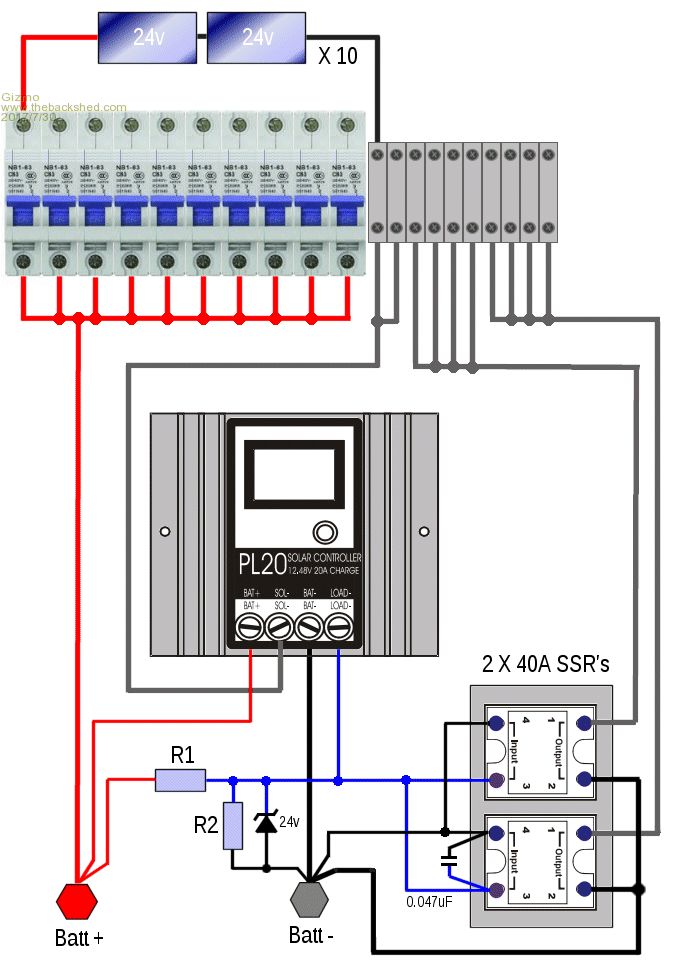 There are a couple of fans to cool the PL20 and SSR heatsink. I'm using a crude series regulator and simple fan control circuit. The MOSFET in the series regulator needs to disipate about 10 watts when both fans are running, so its mounted on the SSR's heatsink. This condition would only happen with full sun. The thermisters are mounted on the PL20 and SSR heatsinks. Its simple, works pretty good. I found a couple of PC fans that draw less then 100mA when running, wait until summer to see if they can move enough air. If not, I'll have to beef up the circuit to drive better fans. Found the fan circuit here. 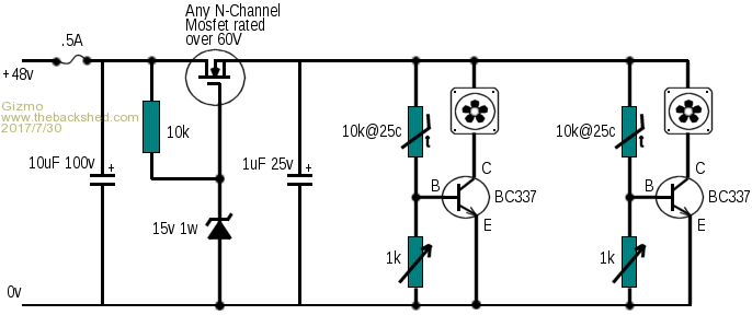 The bits are mounted in a timber box with a glass hinged front. For the glass door, I used a $8 400mm X 300mm picture frame, and built the box to suit. The discrete components are mounted on a piece of veroboard. The solar panels have individual 10amp circuit breakers, handy for simulating cloud cover, etc. 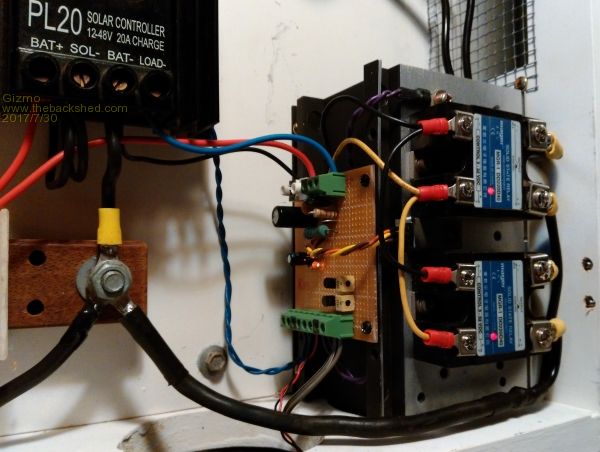 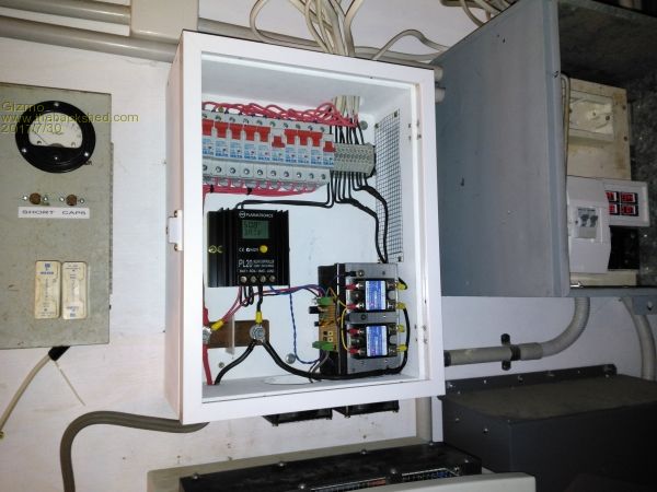 Its all working OK, but I do see some weird behavour when its in Absorb mode. Occasionally its gets into a loop where the PWM output ( on both the LOAD- and SOL- inputs ) resets to off, then ramps up over several seconds, then resets to off, repeat, for several minutes. During this ramp up cycle the battery voltage goes from 54 to 60. Its like it cant find the absorb voltage, set at 58v. I've changed the absorb voltage, current limiting, etc, but these have no effect. In boost and float modes, it works as expected, and if I switch in or out panels, the PWM is stepped up or down to find the new balance. I'll send a email off to Plasmatronics to see if this was a bug or feature. Glenn The best time to plant a tree was twenty years ago, the second best time is right now. JAQ |
||||
| Gizmo Admin Group Joined: 05/06/2004 Location: AustraliaPosts: 5078 |
This afternoon I took some CRO shots. This is the solar panel PWM for the panels connected to the SOL- terminal ( top ) and the SSR's ( bottom ). 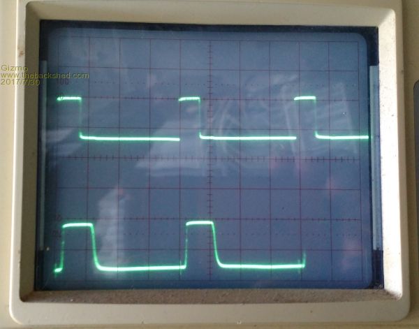 The LOAD- output has a slightly longer duty cycle, which would explain why I needed to set the charge current to 5.5amps instead of 6amps. At the time of the photo the charger was in float mode. Here's the LOAD- signal, with respect to ground. The LOAD- is actually off at this time, its been pulled high by the resistor. The noise isn't on the +48v line, its coming from the LOAD-. This is with the 0.047uF cap in place. Without the cap the noise was enough to false trigger the SSR's 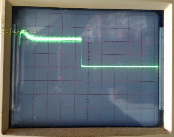 Looking closer. 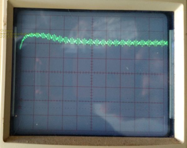 I noticed the glitch I saw in absorb mode also occurred in float mode. Seamed to happen after a big load on the inverter kicked in. The battery bank is fully charged at this stage, so its voltage will rise quickly when the full 30 amps is applied. Watching the PWM on the CRO, I see it steps up the PWM about 3 times a second, so can take several seconds to react to a big change in voltage. It steps up the PWM till it reaches a peak about 4 volts above the desired, then starts to step back down, but after a few steps resets to zero and starts again. Maybe the code decides if it cant pull down the battery voltage quickly enough, better to restart at zero and try again. Glenn The best time to plant a tree was twenty years ago, the second best time is right now. JAQ |
||||
Revlac Guru Joined: 31/12/2016 Location: AustraliaPosts: 1022 |
Nice tidy setup there Gizmo.  I'm not familiar with the pl20 My friend has an old pc2410 it seems to just dump full panel voltage into the batteries always for 5 seconds then shuts off when on float, not much pwm. I think what is happening with your pl20 is that it doesn't expect the battery voltage to rise so fast as it was built for 20amps, with the SSR's running the extra panels maybe it cant respond to a fast voltage rise then stops and restarts, if there is some way to speed up the voltage regulation (less time delay)on the charge controller that might help. Though I do Hope that I am wrong about that as I don't know a quick fix. I think i will try out that fan control circuit when things heat up a bit. I have to say RPC has done quite a lot on renewable energy over the years Cheers Aaron Cheers Aaron Off The Grid |
||||
| Gizmo Admin Group Joined: 05/06/2004 Location: AustraliaPosts: 5078 |
Hi Aaron I've had a serious case of the flu for the last week few days and haven't had a chance to email Plasmatronics or do further investigating. The plan was to have a system that could manage the full array. That way I can still charge on a overcast day, without the manual process of switching in extra solar panels and remembering to switch them out when the sun comes out. And for days of full sun, the controller trims back the PWM to limit current and correctly charge the batteries. My battery bank is to small for the panel's full output, so some serious current limiting needs to happen I'll see what Plasmatronics say, then maybe look at other charge controller options. Now that I've see how the PL20 works, I can modify my old charge controllers software to do the same job, but with the capability to correctly handle the full 70 odd amps the array can pump out on a summer day. Glenn The best time to plant a tree was twenty years ago, the second best time is right now. JAQ |
||||
oztules Guru Joined: 26/07/2007 Location: AustraliaPosts: 1686 |
Well this is another option.... and significantly better than your current setup I think. 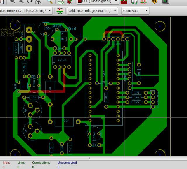 This is an image of a Kicad file I am now using so others can download the files directly and modify or print or manufacture them... no-one seems to have protel. This will do what you want and a whole lot more..... be a week or two before I finally get to do a full story from start to finish. WARNING this is not tested as they have not returned from China as yet... at $5usd for 10 boards, I decided to run them blind. They will be tested as soon as they turn up. I finally got it into a box... It will do your power very easily.... seen it well over the 100A mark Here it is after just getting to bulk from prebulk.. the HOT water had been dragging it back for most of the morning....7kwh or more. That one is using the board on the other thread, and the software there. The three leds are labeled wrongly, but describe the bulk, absorb and float from top to bottom. Not counting the box, the unit itself was probably $30 at the very most. ... probably less if the truth is known. Thems evil looking waveforms.  Village idiot...or... just another hack out of his depth |
||||
Revlac Guru Joined: 31/12/2016 Location: AustraliaPosts: 1022 |
HI Glenn Battery bank too small for Panel output. I remember now I had that happen when I started off grid, had small 100Ah lead acid, 2kw panels, 48v battery bank, running well until I triggered the equalize setting all good at first, then just after some cloud cover there was a lot current going to those small batteries so the voltage went over the limit and the little inverter shut down from over voltage. I have 260Ah lithium now and run at 53.3v never see it go above 54v with 5kw of panels under any situation, so Im happy with it so far. Be handy when it looks after itself, Will see how you go anyway.  Thats looking good there OZ. Just bought 2 of those LCD current meters, I have no idea about this digital control stuff yet. I use Diptrace, but this keycad looks good. Cheers Aaron Cheers Aaron Off The Grid |
||||
oztules Guru Joined: 26/07/2007 Location: AustraliaPosts: 1686 |
Yes CERN is helping with developing it... so I figured it must be good...... They certainly think differently to protel and altium... I swore a whole lot doing that board. I didn't do a circuit/use the schematic editor first, which made it much more challenging than it should have been, but I have built all the footprints I need now, so it is easy.... I killed off all the hundreds ( over 400 I think) of libraries and thousands of footprints it came with.... they would be horrified...... just too much to wade through for me.... take all day to find a part. That thing will hold very very stable voltage under all circumstances.... it is rock solid... within 5/100ths of a volt when set.... (not sure of my meters, so that 5 hundredths of a volt could be not exactly where I think it is....) but if I set it with a real volt meter, it would be very accurate. There is some temp drift though.. and I dont care really... it is very small in relative dimensions. The 350vdc GTI version was just as stable, which surprised me quite a bit.... very handy to be able to have the panels a long long way away. .........oztules Village idiot...or... just another hack out of his depth |
||||