
|

|
Forum Index : Solar : PL20 + SSR 12V Solar Install - High Amps.
| Page 1 of 3 |
|||||
| Author | Message | ||||
wallablack Senior Member Joined: 10/08/2011 Location: AustraliaPosts: 164 |
I am just planning on installing a 12V off grid system and would love some input on it. There is probably a few mistakes and a few things that will need to be changed. I would like to keep this post alive and give everyone frequent progress reports and pictures (small) as I believe it would be good to share basic install measures and ideas. I apologize in advanced if the main schematic below is a bit large on the upload side but I wanted it to be clear to avoid confusion and extra questions. I already have the following for this installation: 200W x 12V Solar Panels (X4)(All 4 are same brand and same age) 120W x 12V Solar Panels (X4)(2 are 2yr old and 2 are 1yr old - Same Brand) Plasmatronics PL20 100A Solid State Relay (Jaycar CAT. NO. SY4086) – Input 3-32V, Output/Load 0-30V 2 x Heat Sinks for SSR and PL20 – (Jaycar CAT. NO. SY4085). Powerstar W7 Chinese DC to AC Inverter (12V 3000W Continuous) 12V Battery Bank @ 798AH consisting of 6 x 2V 798AH (@ 25hr rate) BP Solar 2P1110 Lead Acid Batteries. 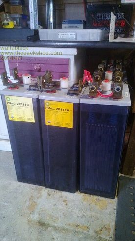
Before I start the rant a lot of you would just say save your cash and buy a PL60, go for a 24V system etc. etc. BUT, I have a few PL20’s on hand from some damaged trailer traffic lights, and I would like to utilize them and the PL20 is IMO the best thing created in the solar world. I have a few SSR’s at 60A and 100A and I would like to utilize them too so there will be no great outlay. Also in regards to going a 12V system is simple, I have 12V panels and a really good set of 6 2V batteries so I may as well utilize them too. In the later days I might take this system to use in an off grid shipping container holiday home I am planning. Also I have a ton of 12V gear to utilize. Here is a quick schematic which I think is “semi right” but some things may need altering…I will get to a few questions later. 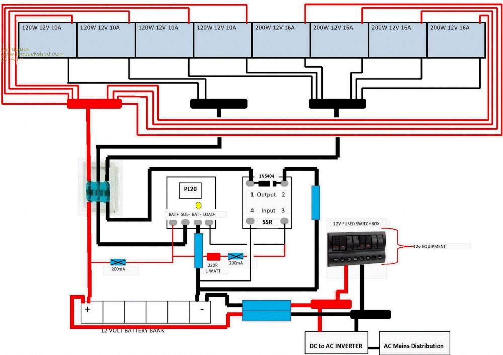
The wire size is indicated in the drawing and I have left it as simple as thin lines are smaller wiring (of differing gauge) and thick lines are large wiring (of differing gauge), obviously red = positive and black = negative. Large rectangular blue boxes are breakers and small rectangular blue boxes with an X through them are fuses...except the NT 1 3 way fuse holder which is the first protection from the solar array. And here is a Plasmatronics schematic for the additional SSR. I am led to believe that this was a schematic drawn up by the good people at RPC (Rainbow Power Company). 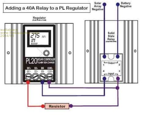
Main Questions. 1. Am I better of running ALL of the positives and ALL of the negative individually from these to my control board and the combining them together, some for the PL20 and some for the 100A SSR. OR, am I better off combining them on the rooftop (one lot as 20A for the PL20 and the rest for the SSR. I feel that it would be better having this all on my control board as I have more flexibility to change as I go. 2. I am set with having a manual solar shut down so if the need arises to do any alteration (or emergency) I have control of this, I wish to do this pre breaker…or should the breaker be enough…why have voltage drop of an unnecessary shutdown switch is one thing I think about. 3. I am also set with having breakers/fuses on both the positive and negative but is it really necessary? As the PL20 & SSR control on the negative I think the answer is yes. So after the bus bars there are three breakers/fuses, one for the main positive which goes directly to the positive of the battery bank and the other two negatives that go to the PL20 and the SSR. Would I best be using a 3 way NT 1 fuse holder which has the manual pull down disconnect. 4. As mentioned I have a ton of 12V gear to run. LED lights, a fridge etc. etc. so I think the positive and negative bus to fuse/switch box is the way to go. The AC distribution I will leave to the local sparky of course. 5. Where do I locate the shunt to get a measure of the amps through the SSR? I am thinking that on the battery negative to SSR “2”output cable. 6. I want to run a small 12v fan to cool the SSR but trials that I have done with any fan prove that most 12V fans cannot handle 13/14V plus volts for very long and live a short life. I was thinking of putting a resistor on the positive lead of the fan. The fan I want to use is a 12V 0.20A. I would intend on connecting the fan as desired as when it gets hot here, it gets hot. The PL20’s heat sink was really hot the other day when it was 45 degrees so every little bit of help in cooling would be beneficial, and let’s face it, in that sort of sun a .2A voltage loss is no great drama. On the heat side of things I have actually modified one of the PL20’s to mount to a much bigger heat sink to help this situation. You can see the difference in heat sinks in the below picture. 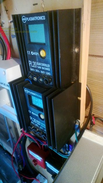
7. The “Catch Diode” that connects to the SSR is a 1N5404. Plasmatronics/RPC (Rainbow Power Company) literature to add the SSR say, Quote “catch protection diode should be placed across the output of the solid state relay (band of catch diode to the battery negative side” Unquote. With most other callings for a catch diode with Plasmatronics PL20 applications it calls for the band to go to the positive side…..Is someone able to clarify this for me? 8. The same literature states, Quote “Extra connected solar arrays will need reverse blocking diodes (unless the SSR relay uses a reverse blocking design)” Unquote. Obviously the SSR has all of the extra solar connected to it but it is only the negative of the solar. Do I need to put the diode in this line? Every time I have used a stud diode it has been in the positive line. 9. The 3 way NT 1 fuse holder/disconnect is what I want but the solar negative that feeds the PL20 will only require a 25A fuse (20A x 1.25 = 25A)…I don’t think there is a 25A NT 1 fuse available. DISCLAIMER: Just because I choose to do this 12V installation myself does not leave any of the following comments to be true or correct. ANY electrical voltage, AC or DC, High or Low Current, should be considered dangerous and potentially fatal. Any persons making comments on this topic cannot be held responsible for any issues whether it be damage to persons, property or data. ALL electrical work, either AC or DC voltage should be carried out by a licensed technician legal to do such work in your area, state or country by laws, regulations and rules set out by the previous mentioned. Any work carried out that follow the below mentioned literature, by any person, licensed or unlicensed is onus of the person/s doing such work mentioned below. ANY LITERATURE BELOW SHOULD BE CONSIDERED FALSE AND INCORRECT. I would like to thank anyone in advanced for their input to my project! Foolproof systems do not take into account the ingenuity of fools. |
||||
Madness Guru Joined: 08/10/2011 Location: AustraliaPosts: 2498 |
You should read this link regarding the powerstar inverter. They use a lot of power on idle this tells you how to fix it. If down the track you decide to go to 24 volt you can use your 2 12 volt charge controllers, just have 1 connected to one half of the battery bank and the other to the other half. If you try scrap metal dealers you can buy heavy cable at a reasonable price rather than running lots of smaller cables from your panels. There are only 10 types of people in the world: those who understand binary, and those who don't. |
||||
wallablack Senior Member Joined: 10/08/2011 Location: AustraliaPosts: 164 |
Funny you mention that link Gary...I have been following it with some interest. My reason for running individual + and - cables into the control box was mainly so I had some control over the connection of the system. I will be running 4 or 6mm^2 from each panel which will connect to the appropriate busbar. This will be split by the negatives to either the PL20 or the SSR. Foolproof systems do not take into account the ingenuity of fools. |
||||
| norcold Guru Joined: 06/02/2011 Location: AustraliaPosts: 670 |
As you know I belong to the 48v, name brand inverter, high AH battery rant group. I am totally off-grid and know the KISS principle adaption is what has made my system reliable and (time will tell) long lifed. That's my disclaimer, love yours. But can understand where your coming from, that battery bank really dictates your voltage, not the solar panels they can be wired in series, or moved on to a larger system later. Just a shame you haven`t 4 times those batteries. Although being BP Solar they are probably aged a fair bit. Batteries are the heart of any system,and if those are in fact getting on in age would suggest you check them out completely before committing to much coin to this project. I cannot emphasise too much batteries are the heart. You cannot successfully add to them down the track, mixing new batteries with old is a definite no-no. The PL20`s (top gear) use relays and shunts, except with relays and shunts there goes the KISS principle. Fuses and quick connect, I`d go for a Jean Muller or similar manual fuse and quick connect all in one on the positive between batteries and PL20`s. Simple, effective, safe. KISS. Wire your panels in series to suit max allowable PL20 input voltage. This cuts wire size reqd and adds efficiency KISS. Have banks of them each with a DC resettable circuit breaker just before PL20 and if your really serious invest in a diverter or two, in case of lightning strikes. Not so KISS. But hey give it a go once done properly you`ll never look back. We come from the land downunder. Vic |
||||
| davef Guru Joined: 14/05/2006 Location: New ZealandPosts: 499 |
Madness, Thanks for posting that link. I also found that on my PowerMaster PM-3000L inverter that I needed an external filter to stop switching rubbish from confusing my solar controller. wallaback, 1) I do the same mainly to have everything come back to a "single point earthing". I thought I was getting unwanted rubbish into some of my measurement circuits, but it turn out to be the same issue as mentioned above. Still I think it be better to reference everything to this "golden point" as you don't have to worry about voltage drops affecting your measurements. And you can disconnect individual components without upsetting the others. 2) Voltage drop across switches. Haven't got any switches! Voltage drops across fuses and circuit breakers are much higher, so I consider those. 3) See #2. What does the 220 Ohm resistor do? If the control fuse to the PL20 (Batt +) blows then the SSR stops working, is that OK? 4) 5)I'd say yes, that way you don't measure any current used by the SSR 6) Kinda surprised that a nominal 12V fan can't handle 13 to 14Volts. Our equipment was rated to 16Volts and I don't recall fan failure attributed to over-voltage. Will a 24V fan work at 12V? 7) I am familiar with "catch-diodes" across relay coils to protect the transistor that switches it, but I would suggest you have to get this right! 8) As far as I am aware all modern solar panels have reverse blocking diodes in them. Maybe, try an ohmmeter check? Cheers, davef |
||||
| yahoo2 Guru Joined: 05/04/2011 Location: AustraliaPosts: 1166 |
Looks like you are pretty much all over it design wise. Panel to battery bank ratio is right at the charge limit so you couldn't have planned it any better. Keeping the number of connections exposed to potential high amp loads is also excellent. Only thing I would suggest is to think about the solar panel wiring. If you wire both the positive and negative out one end there is a large difference in wire length between panel 1 and panel 4 using a two into one pv connector and daisy chaining them, and there will be sections of wiring over the practical current limit on the 60 amp bank. The last 12 volt system I upgraded with extra panel banks with an eye to converting to 24 volt in the future I linked the positives out one end and the negative out the other (to keep the wire length the same to each panel)then fitted a heavier gauge wire in the connectors on the sections that take the full bank load. It seems to work OK and I can change to 24 volt in a few minutes with the existing wiring and connectors. Fault finding solar panel wiring on an old crusty flat mounted system on a sloping roof is one of my all time least favorite jobs, specially when the bolts on the clamps are all rusted solid. I'm confused, no wait... maybe I'm not... |
||||
| Warpspeed Guru Joined: 09/08/2007 Location: AustraliaPosts: 4406 |
Cable sizes do not really mean much without knowing the distances. Obviously either 4mm^2 or 6mm^2 will carry 16 Amps easily, but voltage drops are another matter. Lets see... 4mm^2 will have a resistance of .0172/4 = .0043 ohms per metre. At 16 Amps that is 68.8 millivolts per metre, or actually twice that (two wires). So figure on 137.6 millivolts per metre. That may or may not be a lot, depending on how far it has to go. 6mm^2 cable will be .0029 ohms per metre At 16 amps thats 46.67 millivolts per metre x2 is 93.3 millivolts per metre for two wires. Ten metres of the thicker stuff is just under a one volt drop at 16 amps. 10mm^2 works out to .00172 ohms per metre At 16 amps 27.5mV x2 or 55mV per metre for two wires. Thats just over half a volt drop for 10 metres. That may be more realistic, but how far do these wires need to go ? Cheers, Tony. |
||||
| yahoo2 Guru Joined: 05/04/2011 Location: AustraliaPosts: 1166 |
This is roughly what I am talking about. 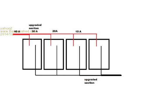
I'm confused, no wait... maybe I'm not... |
||||
wallablack Senior Member Joined: 10/08/2011 Location: AustraliaPosts: 164 |
I would love to go 48V Vic….but that may be in the future I think. I am also a fan of keeping it simple with less to go wrong. I only want to do this exercise as I have just about everything on hand and it will be a great learning curve with some good quality components. My issue on the fuse side of things as if I went for a Jean Muller / NT 1 style fuse is that the two negatives that come from the solar to supply the PL20 only need to be 25A and I cannot find a NT1 25A fuse anywhere. 3. I would prefer the SSR stop working than the PL20 or anything else gets damaged. In my eyes if Plasmatronics suggest it, I will follow it. 5. Exactly what I thought too, thanks for your input. 6. I have gone through a few fans at 12V….maybe 5 – 8, even one from a used 28V – 55V chinese GTI. Might be work investing in some good quality 12V fans with good bearings etc, on my research they more expensive ones actually use less current too so that’s another bonus. 7. I will be using a 1N5404, as again Plasmatronics recommend this diode. 8. The diodes are Schottky diodes for protection which are completely different to reverse protection diodes. Am I correct? The panel to control wiring is my confusing bit. Just an insight. Wher the control board will be located is directly below where the solar panels are mounted so the distance from say the CENTRE solar panel on the array is probably no more than 2 metres away from the control board. I really want to bring each solar panels + and – directly to the control board so I can have more control (actually more tinkering). Figuring that the farthest panel from the control board will be say 5 metres. VERY good food for thought. As I mentioned above relating to distances the cable will make quite a difference. Nice idea…. Foolproof systems do not take into account the ingenuity of fools. |
||||
wallablack Senior Member Joined: 10/08/2011 Location: AustraliaPosts: 164 |
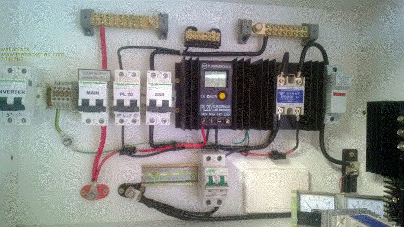
Well I have made a little bit of progress...I love holidays! Question: Am I killing it with the use of only one side of the circuit breaker? These are what I had available to me. IMO I can't see a problem with it but I am no solar installer...I dig dirt for a living...big difference. Ignore the right hand side of the pic, this is 2 rectifiers, another SSR and another PL20 for my wind install which I am all over and it has been in operation...this is just it's new home. I think I have put the shunt in the right spot to measure the SSR output...I think. The two analogue V and A meter were from a 24V wind charge controller, this will be upgraded when I get to town one day... The SSR I have installed there is just a cheaper one, once I have run it all for a while I will put the good one in. Foolproof systems do not take into account the ingenuity of fools. |
||||
wallablack Senior Member Joined: 10/08/2011 Location: AustraliaPosts: 164 |
Quick question..... I live in an area with very high sunlight. I have been testing a PAIR of my new Rich Solar 200W 12V panels... Individually they reach 10A Together they do not get over 12-14A. Simply joining + to + and - to - and testing them at the end of the 800mm lead from the panel. I would understand if it was slightly overcast weather but we are getting some top notch sun today. And another observation (or mistake) in regards to completely different panels.... 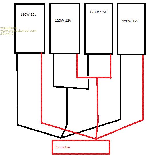
With the above diagram originally installed to two separate charge controllers and then to one charge controller.... All combined I was only getting peak of 25A. Connected with 6mm^2 cable and the controller only 3 metres from where the array was mounted. Peak was most of the afternoon but even when the sun was 90 degrees to the panel and on a 40 degree perfect day it only got to 25A..... Thinking of it now am I right in saying the panels are 120W x 4 = 480W, batteries are at say for example 13.8V. So 480W / 13.8V = 34.8A......only getting 25A so 13.8V x 25A = 345W in perfect conditions. Foolproof systems do not take into account the ingenuity of fools. |
||||
Madness Guru Joined: 08/10/2011 Location: AustraliaPosts: 2498 |
Heat reduces the power output, the cooler your panels the better they work. Today I was not getting over 2300 watts, rated power is 2840. I have seen it go over 3000 after being shaded by a cloud for a while then getting full sun. Still made 17.9 KWH's today. Saw a thing in Jaycar catalogue this morning where someone said putting a spray of water on the panels increases the output. I tried it for a while but did not see it change much, maybe I was not persistent enough. There are only 10 types of people in the world: those who understand binary, and those who don't. |
||||
wallablack Senior Member Joined: 10/08/2011 Location: AustraliaPosts: 164 |
I did the same thing last summer. I put a sprinker on the roof of my shed to keep it cool and it was coincidentally wetting the panels too. There was a 2A rise in output but noting major. I have a 10,000lt tank for the rain water off my shed roof so I recirculated it from that so the water was cool all day long...BUT, do you think the constant water coverage would somehow "shade" the sunlight and have a reverse affect...would be better cooled from the underside with a sprayer etc. Even during the heat/peak of the day I give the panels a good spray/cool and notice a rise in amps. I like the Turnigy watt and power analyzer for good at the moment data, but when the power goes out to it so do the figures. Good to know figures like Watt hours, Watt peak, Amp hours, Amp Peak, Watts Peak...cool little units for "right now" data. Foolproof systems do not take into account the ingenuity of fools. |
||||
Madness Guru Joined: 08/10/2011 Location: AustraliaPosts: 2498 |
I get the data from my Outback MPPT controller, nice bit of gear. There are only 10 types of people in the world: those who understand binary, and those who don't. |
||||
| yahoo2 Guru Joined: 05/04/2011 Location: AustraliaPosts: 1166 |
Are you getting resistance as the batteries charge dragging the amps down? Really need a good consistent load added to test things properly. normally at full load the panels will output close to max amps, the 20-25% loss should be in voltage difference between the panels max output volts and the battery volts. Best thing to do is download the panel output graphs and do the calculations from that. Most of the panels I have installed output3%+ more than their advertised output, due to improved manufacturing and a lack of the lower solar cell grades so sometimes I have struggled to get under the controllers limits but it does make up for some of these voltage "headroom" losses you need with WLA batteries. I'm confused, no wait... maybe I'm not... |
||||
wallablack Senior Member Joined: 10/08/2011 Location: AustraliaPosts: 164 |
I love the Outback gear but the FM80 sits at around $1,100.....for a Charge Controller...bit steep. The PL20 in my eyes can control 120A for $300ish (+ SSR etc) and can still give you really good daily data. It's capabilities are awesome! Foolproof systems do not take into account the ingenuity of fools. |
||||
wallablack Senior Member Joined: 10/08/2011 Location: AustraliaPosts: 164 |
They were solely connected to the battery bank, via controller of course...problem was is were I was testing them...DAAA!!! 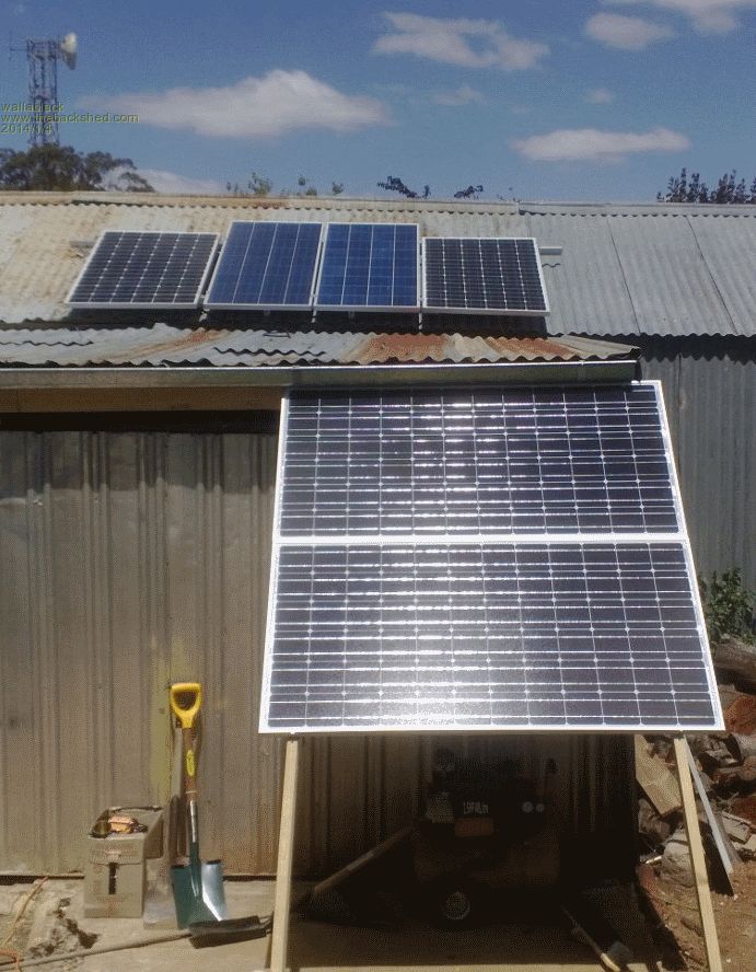
See the guttering is shading a portion of the top panel.....funny how things are easily overlooked. Guess what, I moved them lower and they are really good lol...Good time to test my under panel spray cooling but I'm not because I would like the water recirculated....it's the eco warrior in me. Foolproof systems do not take into account the ingenuity of fools. |
||||
Madness Guru Joined: 08/10/2011 Location: AustraliaPosts: 2498 |
I got my Outback MX60 for $300 secondhand, there is 2 of them on fleabay finishing in a few days sitting on $500. There are only 10 types of people in the world: those who understand binary, and those who don't. |
||||
| yahoo2 Guru Joined: 05/04/2011 Location: AustraliaPosts: 1166 |
I must admit I don't see the point of tweaking those last few watts out of an off-grid system (with water cooling). the panels only run at full power for a few hours, most days they sit idle for most of the afternoon just topping up the batteries. It is winter where an oversized SSR panel bank really shines, no need for cooling then. Having a solar heater tank full of hot water and batteries well on the way to full charge with the dishwasher or washing machine going in the early afternoon on a sunny winters day never gets old in my book. Ironically that is the thing I have the most trouble convincing people about. Why they insist they need bigger batteries so they can run these appliances after the sun goes down I will never understand. Modern appliances come with delay start timers, everything can be done & waiting for you as you get home from work. Great to see the problem fixed, I was going to suggest you check for any shading, but I thought, No keep my mouth shut, I'm the only one that does that, I don't want to look like a complete plonker  I'm confused, no wait... maybe I'm not... |
||||
Madness Guru Joined: 08/10/2011 Location: AustraliaPosts: 2498 |
For me the biggest draw of power is refrigeration. Our front load washing machine with heating element on a 60 degree wash still only uses a fraction of what the fridge uses in a 24 hour period. If you can run things like washing machines when the sun is shining is more efficient as there are losses putting power into batteries and drawing it out again. There are only 10 types of people in the world: those who understand binary, and those who don't. |
||||
| Page 1 of 3 |
|||||