
|

|
Forum Index : Solar : Solar Tracker by Richard Gideon
| Author | Message | ||||
| Khalid Newbie Joined: 23/07/2011 Location: PakistanPosts: 14 |
Hi, I have recently purchased the 450 watt Monocrystaline solar panels. I was searching solar tracking circuits for many days and found different variety. At last after thorough study i found that Mr. Richard Gideon circuit for sun tracker is the best on the website(It is only my opinion). Richard Gideon Solar Tracker Anybody can read above article and can judge how this circuit works. The sad story is that i didn't find any PCB for this circuit so today i spent about 8 hours to build this one. Tomorrow i shall etch and mount the components. 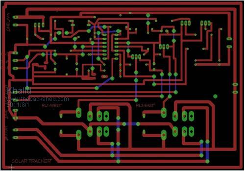
its a Single sided PCB and the blue lines are the jumper wires :) My Projects: www.my-woodcarving.blogspot.com www.free3dscan.blogspot.com |
||||
| Khalid Newbie Joined: 23/07/2011 Location: PakistanPosts: 14 |
Here is the etched version. You can also see the Hybrid system Battery charger and controller circuit. 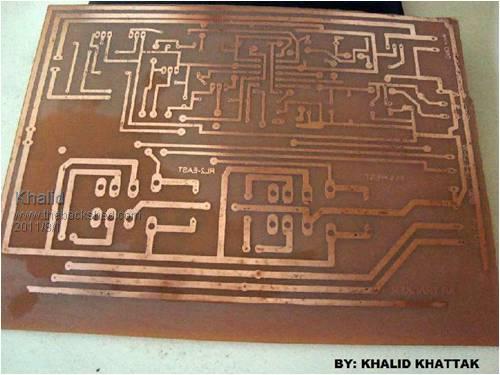
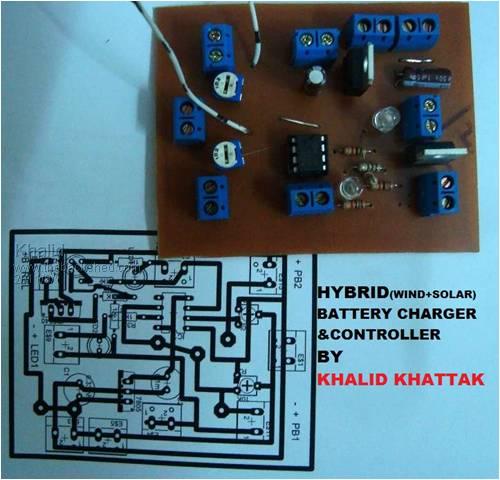
My Projects: www.my-woodcarving.blogspot.com www.free3dscan.blogspot.com |
||||
| KarlJ Guru Joined: 19/05/2008 Location: AustraliaPosts: 1178 |
i give you a 10/10 for the sharing and a 10/10 for the pcb and etching given its someone elses design it cant be your fault if it doesnt work unless you made a mistake in the circuit so good luck, let us know how you go Luck favours the well prepared |
||||
| Khalid Newbie Joined: 23/07/2011 Location: PakistanPosts: 14 |
Hi Karl, Thanks for appreciations.. I have checked the circuit with two LDR's installed . Following are my observations, please consult Picture No.1 in my first post: 1- As per given conditions in sketch for Pot1 and POT2 the LED's can be set. 2- After setting, i found that The motor only rotate when the Right most LED(LED1) is in ON condition. When the LED 2 is On motor do not rotate. i.e. The motor rotate in only one direction. When i press Limit switch West side the motor stop. 3- The LED's react to the lighting environments. 4- Only one relay(the LEFT MOST)work the right relay do not work at all. 5- I checked closely the circuit and found that the right relay is connected wrong so i change the connections for RELAY-EAST as shown in attached picture. 6- After reversing the connection i connected to the power supply but still motor do not rotated in opposite direction:( When i adjusted Trimpot 10K a smoke came out of it. I am not electronic guru but if some one point to me in the right directions. How the connection to be made to the DPDT relay. Please down load the picture 1 and in a Paint program help me drawing rough sketch. I am sharing eagle PCB file here, I didn't made schematic. I directly draw the PCB by manual tracing. Kindly help me. 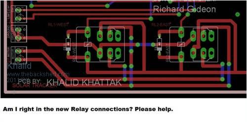
2011-08-01_225806_LM339Solar_Tracker_with_relay.zip My Projects: www.my-woodcarving.blogspot.com www.free3dscan.blogspot.com |
||||
| KarlJ Guru Joined: 19/05/2008 Location: AustraliaPosts: 1178 |
waayy out of my league mate glen is your man  Luck favours the well prepared |
||||
| Khalid Newbie Joined: 23/07/2011 Location: PakistanPosts: 14 |
Okay mate:).. I hope some one someday will solve the puzzle for me..I can wait till death:)  My Projects: www.my-woodcarving.blogspot.com www.free3dscan.blogspot.com |
||||
| conntaxman Newbie Joined: 04/08/2011 Location: Posts: 5 |
I built that same circuit and it didn't work either.I had it were the [i think] west motor would start and keep on running and nothing would change it, I tried to hide both the photo cells, and nothing. Im looking at a different solar tracker but they didn't put all the info in one picture. here is the link. It sounds good.But? http://www.projectcircuitpack.yolasite.com/automatic-solar-t racking-system.php John anyone have a good circuit |
||||
AMACK Senior Member Joined: 31/05/2009 Location: AustraliaPosts: 184 |
Hi All, My self and Downwind built a tracker that works well is still working now. We looked at light cells and went for a timer chip (RTC) as a few dont work  and there is always the overcast day there is will spend all of it's time looking for the sun. and there is always the overcast day there is will spend all of it's time looking for the sun.
Just a thought.. I did post a few photos of it here. Amack *Note to self 1. Make it thick 2.Make it heavy. 3.Make it stronger than it should be. 4. Don't rush the first job as the second job will cost more and take mor |
||||
| Khalid Newbie Joined: 23/07/2011 Location: PakistanPosts: 14 |
John Tulloch, helped me understanding the Richard Gideon circuit. This is email correspondance i am posting so that everybody know how the circuit work. Hi Khalid. I saw your solar tracker on the backshed.com.au I no longer post there, but can answer some of your questions. 1.Yes the rewire on your relay should work. The original did not change the direction , but mimicked the first relay. 2. If you got the two leds to flash, as the setup conditions provide, you have it working.... mostly. 3. Looking at the circuit, the tracker does not actively track the sun, but instead uses a (probably better) system, where by, no matter what you do to the shading of the leds, it will only go further west until it hits the stop.... it will not go east while there is light available. Look carefully at how the op amps/comparators work. The west motor relies on a balanced input on pins 4 and 5. If the east sensor sees more light it just drives the pin 4 high (-in), which drives pin 2 low.... stops west motor. As the sun moves west, the west sensor gets more light, this drives pin +5 in higher, this drives pin 2 higher, and the west motor moves until the sensors are equal or biased to the east of the light point.... and waits until the west sensor is stronger and repeats. There is no provision for "hunting" ie trying to correct for being too far west.... it just waits until thesun moves further west, and the west sensor gets more light than the east, and so moves..... it does not track backwards as I see it. When it can no longer track any further west, the limit stops the motor (shorts Q1 base)....... and it must wait until it gets dark..... ie no light..... why? 4. The voltage divider set by VR2 will hold the pin 9+ (in) at a preset voltage from VR2. This is compared to the voltage from the sensor west. As long as there is enough light to keep pin8 -(in) above pin 9 then the east motor stays off. Only when the light fades and pin 9 ends up having more volts than pin 8, will the east motor start to run. When pin 9 has more volts, pin 14 goes high, the led comes on, and a separate transistor drives the east relay simultaneously from the same drive signal off pin 14 (out)........ so if you got the east led to come on at some stage, then the relay should have as well....... also, some of the output is sent to another comparator (1d) to hold the west motor relay off while this is happening.. ie pin 10 (-in) goes high, so pulls pin 13 (out) down... which pulls pin 1 (out) down which shuts off Q1 while the east relay is running. quote " 1- As per given conditions in sketch for Pot1 and POT2 the LED's can be set. 2- After setting, i found that The motor only rotate when the Right most LED(LED1) is in ON condition. When the LED 2 is On motor do not rotate. i.e. The motor rotate in only one direction. When i press Limit switch West side the motor stop." If you got the two leds to function, then the relays should have as well. The one wired wrong would go the same way as the west drive. If the relay did not respond at all, then check the transistor or the relay itself for open circuit on the solenoid. Use your meter to track where the voltage stops. Does it get to the input side of the 4k7 resistor driving the tranny (r18) (it should as the led 1 lights according to your reply) does it get to the base of the tranny? (Q2)..... is the limit switch shorting the input to the tranny.... it's there somewhere, as the led shows that the comparator is driving the leds tranny (Q3). The west limit switch won't stop the east relay, as it only shorts the base of the west driver tranny. The east limit switch shorts the east driver tranny separately. Does the east relay click?. The reversing circuit (relays) are not well done, as if both are turned on, it will short the battery. It would be better wired differently, but it will certainly work as it is. The smoke coming out of VR2 tells me you have the pot turned 120 degrees around. Is it is in the right orientation? It cannot short the 9v to ground, as the wiper only goes to a high impedance input. For it to smoke, you must have the wiper capable of putting ground to the +9v.... check your orientation of the wiper position against the circuit.. It should not have damaged anything else but the pot. Feel free to reproduce this in whole or part in your response on the site, it may help some others who did not get it to work as they thought it would. I think most would think it should dither back and forth to track the exact position, but I don't see that in the circuit. It is ONE WAY while there is light (west only), which I think is probably better than trying to track the shadows of the clouds. It will only progress westwards, not run back and forth trying to find the sun on a cloudy day..... just gradually follow the sun westwards, or wait until a big enough difference between the east and west sensors give it enough potential difference to progress. East is only when the light no longer hits the west sensor at all (dark... not just shade.... VR2) Have fun John Tulloch Flinders Island AUSTRALIA My Projects: www.my-woodcarving.blogspot.com www.free3dscan.blogspot.com |
||||
| Khalid Newbie Joined: 23/07/2011 Location: PakistanPosts: 14 |
Hope it was of some help Khalid. "> your question my East relay never clicked. No response from east relay. I have to check it. Thanks" If while ever led1 lights, it will stop the west relay (push pin 1 for Q2 low), and drive the east relay.... so if the led is on, your close to finding why the relay does/did not click.... short the collector to the emmitter on the Q2. This should drive the relay on.... if not, then check for + volts on the relay. Q2 only shorts the other end of the solenoid to ground. Hi, I forget to answer your following *"When it can no longer track any further west, the limit stops the motor (shorts Q1 base)....... and it must wait until it gets dark..... ie no light..... why?*" This is because we have a good amount of energy even the sun is in horizon sometime called twilight.. The solar panel extract the juice until it is completly dark even 1 or two hours of sunset in some ppart of the world. NO...... it was a rhetorical question, which I answered for you... This is why : 4. The voltage divider set by VR2 will hold the pin 9+ (in) at a preset voltage from VR2. This is compared to the voltage from the sensor west. As long as there is enough light to keep pin8 -(in) above pin 9 then the east motor stays off. Only when the light fades and pin 9 ends up having more volts than pin 8, will the east motor start to run. When pin 9 has more volts, pin 14 goes high, the led comes on, and a separate transistor drives the east relay simultaneously from the same drive signal off pin 14 (out)........ so if you got the east led to come on at some stage, then the relay should have as well....... also, some of the output is sent to another comparator (1d) to hold the west motor relay off while this is happening.. ie pin 10 (-in) goes high, so pulls pin 13 (out) down... which pulls pin 1 (out) down which shuts off Q1 while the east relay is running. The twilight will only delay the process until pin 9 (set voltage) becomes more positive than the fading light driven pin 8- Pin 8 goes less positive as the light fades. When the inverted input drops below the + input, the comparator goes high on the output.... and drives the east motor. Have fun, I may get a chance to look at the other tracker later on. John Tulloch Flinders Island AUSTRALIA My Projects: www.my-woodcarving.blogspot.com www.free3dscan.blogspot.com |
||||
| Khalid Newbie Joined: 23/07/2011 Location: PakistanPosts: 14 |
And here is my other dual axes sun tracker circuit by Hans. Regards 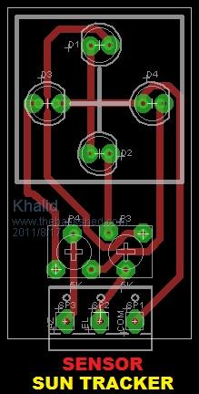

My Projects: www.my-woodcarving.blogspot.com www.free3dscan.blogspot.com |
||||
| conntaxman Newbie Joined: 04/08/2011 Location: Posts: 5 |
Sun tracker starting to track my mind. This is my 4th time to rebuild the cir.The last time i have both leds light, but the Q3 led is very bright compaired to Q4 and I cant adjust the brightness. I also checked the voltage of my L7809 and im only getting 3.81 volts.suppose to have 9vdc. when I shine a flash light over each photo cell the led's do get bright and go back low. But the motor Never stop running, it;s the west relay that keep pulled in. Has .... ANY ONE... got this cir working....?????? with out any modifications. Im getting to think someone put this cir. up just to make every one go nuts, that dosent know electronics really ,really, really good. he he he . Plus checking different voltages, I smokes up a wire, and now I have to go and check all the parts out.What a pain. Those from that place red rock for 50 bucks are getting to sound pretty cheap. I spent over that all ready and still have not got it working right. Well now its time to have a beer, maybe a FEW, while taking it all apart. If anyone got it working Take a picture of it and post it.ha ha ha Wonder if that person ever finished the pc board for this thing.I know he had trouble with the relays.Plus I wonder why they used spDT. it seem that you only need spst.All the wires do is chris cross on the poles. John Nice board. |
||||
| Khalid Newbie Joined: 23/07/2011 Location: PakistanPosts: 14 |
Hi John, I am still in the business... I have posted the details of correspondence with expert above.. The Motor will always move west, you have to adjust dead band by playing with POT...I abandoned that circuit for ever... Now i am going to make my own circuit using ATMEGA328 micro-controller.. I hope this will be much user friendly with less components... My Projects: www.my-woodcarving.blogspot.com www.free3dscan.blogspot.com |
||||