|

|
Forum Index : Solar : Modified Solar System.
| Author | Message | ||||
| Turion Newbie Joined: 28/05/2024 Location: United StatesPosts: 2 |
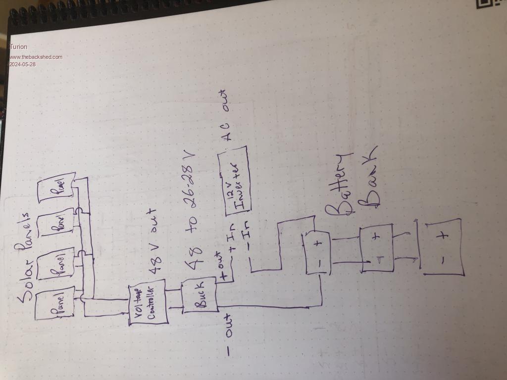
Greetings from the mountains of California, USA. When my dad moved to the mountains 30 years ago and set up his own solar system with parts he cobbled from hither and yon, one of the things we did (later) was to set it up as a potential based system. It was composed of solar panels, a controller/regulator, a buck module, an inverter, and a battery bank. There was some switching I will get to in a moment, but basically a very simple system. I have been looking over sone of the stuff going on here, and you folks are way beyond me, but I am in the process of setting up solar on my own place at the moment, and have every intention of setting up a similar system. I also have a friend, Bob French, that I shared this basic idea with when he lived back east. He set it up on the small system he had at his cabin and was very, very, VERY happy with the results it gave him. For those not familiar with a potential based system, here is a short video where I show how to run loads between they positives. Runniung on the Potential Difference All it does is take advantage of the fact that many electrical devices work simply because you send voltage and amperage through them. They don't care where it goes once it has passed on through. They don't "convert it to mechanical energy" as we have been taught. They wouldn't work this way if that was true. So you can send it through a load to ground where it dies the way most folks do with DC circuits, or send it to a lower potential positive to charge it. Your choice. Does ALL of the energy input THROUGH the load make it through and out the other side to charge the battery? NO IT DOES NOT. But you CAN extend run times with this kind of system, and when you are trying to make your charged up batteries last as long as possible, especially when they are the ONLY source of power other than the sun, it makes a lot of sense. In the case of his solar system, we bucked down the output of the controller/regulator and sent it THROUGH his inverter and out the other side to the battery bank. The inverter ran while the battery bank charged, but MUCH of the energy that went through the inverter was recovered in the batteries and they charged up. They didn't charge quite as FAST as usual, but he was running his inverter the WHOLE TIME. At the end of the charge period there was a double pole double throw switch or two that hooked the inverter up the normal way to run off the batteries. Now later on, as things changed and improved, he was able to eliminate the buck module completely and control the output voltage with just the voltage controller, but I included it in the drawing because that's what we had at the beginning. That's about it. I was hoping with all the great minds here that you guys might have enough experience with solar systems, charge controllers, inverters and buck modules to put together a really efficient system that I can take advantage of as I add solar to my place. You know, you do all the work and I reap all the rewards. Actually I am working on some stuff right now, but the folks here will probably put what I have done to shame.  |
||||
| rogerdw Guru Joined: 22/10/2019 Location: AustraliaPosts: 852 |
Hi Turion, welcome. So I watched the video and I heard you say that the (larger 12v) battery voltage would continue to rise ... and the (smaller two 12v series) batteries voltage would go down. I assume you've done spreadsheets comparing the current levels between different configurations ... and have come to a conclusion that you haven't spelled out for us yet. So are you saying you can get the same amount of work out of the battery ... but by configuring it all this way ... also get the benefit of it charging an extra battery ... ... and at the same time having the same discharge rate of the smaller series batteries ... or a marked increase in discharge of them? Is this what is called "the loving giving path"? I can see the correlation between the motor drive video and the solar circuit you provided ... do you have any real numbers to share or is this all mostly theory? Thanks ... and all very fascinating. Cheers, Roger |
||||
| nickskethisniks Guru Joined: 17/10/2017 Location: BelgiumPosts: 458 |
Very welcome indeed, interesting schematic you've drawn. Your dad probably knew what he did and had his reasons to set something up like he did. As an experimental guy myself I would advice you to keep your drawing just for experimental use only until you've proven yourself the reliability of the system. Can I point some things out? We came a long way since 30y ago, technology improved and so has availability and costs of equipment and parts. I can be wrong but since you post this kind of "electrical" schematic and no "electronics schematic" I have the feeling you don't have a lot of "hands on" experience with this stuff? (we will be happy to assist you  ) )Are you able to ask your dad why he did it like that? This might be the most important question for you to ask. If I would take a guess, it's because he had no compatible parts. He had 48V solar panels a 48--> to 24V buck, and 12V inverter. He wanted to use all the produced energy and didn't want to covert potential energy/voltage to heat. So above is a clever way to do so, BUT he might have added protection circuitry like perhaps zener diodes over the batteries and inverter preventing them to being overcharged/volted. The charging current will completely depending on the inverter current pulled. So if the load is little the charging current is little, unless you imagine a zener diode over the inverter input this would only limit the current true the batteries provided by the regulator max current. Overnight you can connect the inverter directly to the battery. The logic behind is very well know and more complex circuits can be calculated with thevenin/krichoff/etc. May I ask for some more details about power/ currents involved? If I would only have those given parts I would adapt the buck converter to output 12-14V to charge the battery with maximum efficiency and connect the inverter directly. If you want to build a serious, efficient system, and start from scratch I advice you strongly to build the nano platform Inverter/mppt controller derivatives. |
||||
| Turion Newbie Joined: 28/05/2024 Location: United StatesPosts: 2 |
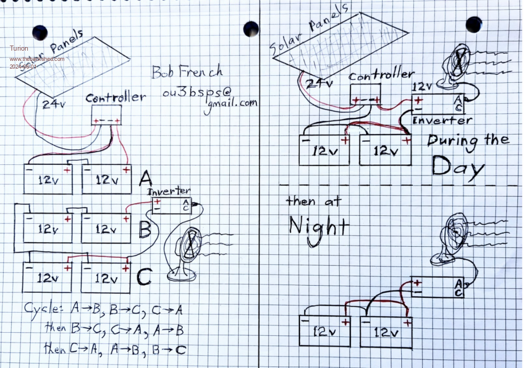
I wanted to let you both know that there were no other components in the setup my dad was running. I know because I helped him put it together and it was based on some things I had been working on, not his work, so he was following my lead, and I was in the dark with no flashlight. All I know is that prior to the changes we made, he could NOT run much of anything during the day and still have enough in his batteries for them to go all night, and would often have to resort to the propane generator. Once we set up the system as shown he reported being able to run loads during the day and almost always having the power reserve in the batteries necessary to get him through the night. Of course that's a generalization because weather is never the same from day to day. I did ask my friend Bob French to draw up what he put together and his drawing pretty much replicates what I posted except he had no need of the buck module. Attached is his drawing and he included his email in case anyone wants to ask him any questions. He used to live in the Eastern US, but now lives in Mexico. We communicate almost daily. He had a VERY small off the grid cabin and did not run much off his inverter. I do remember him telling me that after he set up this way he had to cover one of his solar panels because too much energy was produced. I do NOT remember the specifics of that statement, but if you are interested you can ask him yourself. I should clarify that what I am representing here is basically two things: 1. That an inverter (12 volt) can be run between the positive output of the solar panel charge controller and the positive of a battery bank as long as the output of the charge controller is set to output no more than about 27 volts, which is 14 volts over the voltage of the batteries if they are at 13 volts and wired in parallel as shown in the drawing. 2. That the inverter will run loads while the battery bank charges and more work will be done by the system on the energy input by the panels and the system as a whole, when connected up in this way. The inverter does not "consume" or "convert" the energy that passes through it, but works because of the movement of voltage and current. MUCH of which can be recovered when you run between the positives. That's it. I believe this should be a standardized method of operating charge controllers, inverters and solar panels, but I don't have the technical skills to design that, except in the rudimentary way I have shown here, which you guys have already said lacks sufficient safety precautions. Just trying to share some info. Hope it helps.  |
||||